Long time self-adapting integrative approach

An integral method and self-adaptive technology, applied in the field of integral, can solve problems such as expensive

Inactive Publication Date: 2008-05-14
INST OF PLASMA PHYSICS CHINESE ACAD OF SCI
View PDF0 Cites 5 Cited by
  • Summary
  • Abstract
  • Description
  • Claims
  • Application Information

AI Technical Summary

Problems solved by technology

The accuracy of the digital integrator mainly depends on the resolution of AD or VF, the higher the resolution, the higher the accuracy, therefore, when the digital integrator chooses AD or VF with high resolution, it will be expensive

Method used


Image

  • Long time self-adapting integrative approach
  • Long time self-adapting integrative approach

Examples


Embodiment Construction

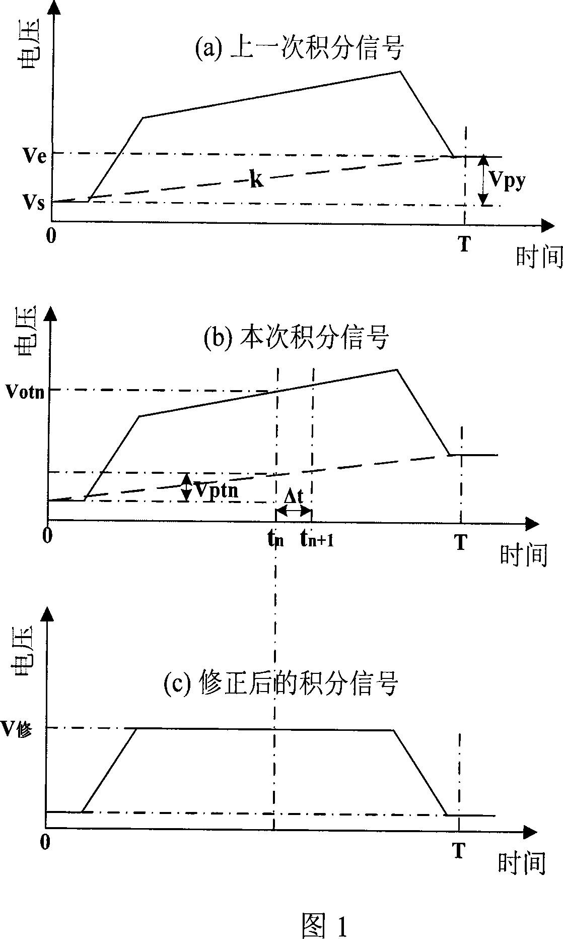
[0019] As shown in Figure 1(a), the initial integration value V at the beginning of the last pulse signal integration is measured. s and the integral drift value V at the end of integration e , and the integration time is T, then the integral drift V within the time T py =V e -V s , to obtain the last pulse signal integral drift rate k=V py / T;

[0020] As shown in Figure 1(b), for each moment t with Δt as the time interval in this pulse signal integration process 1 , t 2 ...t n ..., using the integral drift rate k of the last pulse signal to calculate the integral drift V at each moment of this pulse signal ptn , V ptn =k×t n , measure the output voltage value V of the pulse signal integrator at the corresponding time position otn , to obtain the integral modified positive value V of the pulse signal corresponding to the time position shown in Fig. 修 =V otn -V ptn ;

[0021] Set the drift rate of the first integration to zero.

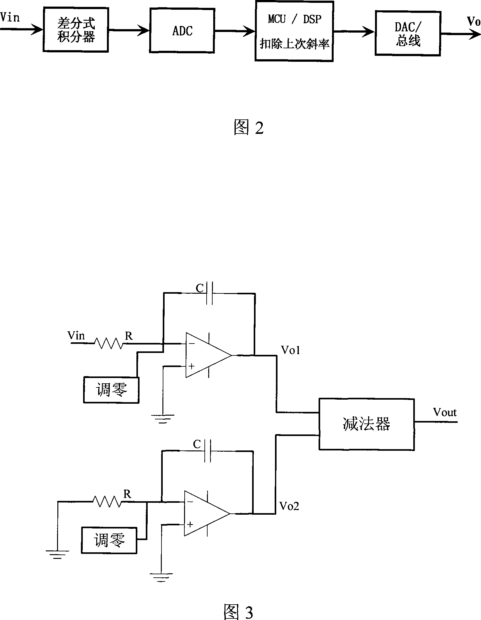
[0022] In the specific implement...


PUM


Abstract

The invention relates to a method adapting integral for a long time, which is characterized in that the last pulse signal integral drift rate is tested to calculate the integral excursion amount at any moment of the pulse signal, and to measure a output voltage value of the pulse signal integrating instrument at a corresponding time, thereby obtaining the integral modifying value of the pulse signal at the corresponding time. The method of the invention obtains the automatic modification to null shift for a long time integral by the manner of combining simulated integral and numerical modification.

Description

technical field [0001] The invention relates to an integral method, more specifically a long-time integral method capable of effectively eliminating zero drift. Background technique [0002] Long-time integrators are mainly used in electromagnetic measurements of some devices. For example, in the process of tokamak discharge experiments, the output of many electromagnetic measurement diagnostic signals is the differential component of the signal. To restore the signal, an integrator is needed. With the continuous development of tokamak nuclear fusion research, the plasma discharge time is getting longer and longer, so the integration time is also required to be longer and longer, even to the order of thousands of seconds. Due to the existence of zero drift, the analog integrator needs to be equipped with a zero-adjustment circuit. Before each use, the integrator is adjusted to the best state through the zero-adjustment circuit, that is, the mi...

Claims


Application Information

Patent Timeline
Patent Type & Authority Applications(China)
IPC IPC(8): G01R31/00G06G7/18
Inventor 季振山王勇罗家融
Owner INST OF PLASMA PHYSICS CHINESE ACAD OF SCI
Why Eureka
Try Eureka