
Partition board drainage hole structure of window air-conditioner

An air conditioner and drainage hole technology, which is applied in air conditioning systems, heating methods, and prevention of condensed water, etc., can solve the problems of reduced cooling efficiency, inability to completely isolate indoors, external air convection, waste of machine power, etc., and achieve the effect of saving electric energy

Inactive Publication Date: 2008-05-14
LG ELECTRONICS (TIANJIN) APPLIANCES CO LTD
View PDF0 Cites 10 Cited by
  • Summary
  • Abstract
  • Description
  • Claims
  • Application Information

AI Technical Summary

Problems solved by technology

[0004] However, since the rectangular drainage hole on the partition plate of the window air conditioner is always open, the indoor and outdoor air can still communicate through it, and the convection of the indoor and external air cannot be completely isolated. For example, when the room is in a cooling state, due to the hot air outside Entering through the drain hole, causing a waste of equipment and electricity that reduces the cooling efficiency of the room

Method used


Image

  • Partition board drainage hole structure of window air-conditioner
  • Partition board drainage hole structure of window air-conditioner
  • Partition board drainage hole structure of window air-conditioner

Examples


Embodiment Construction

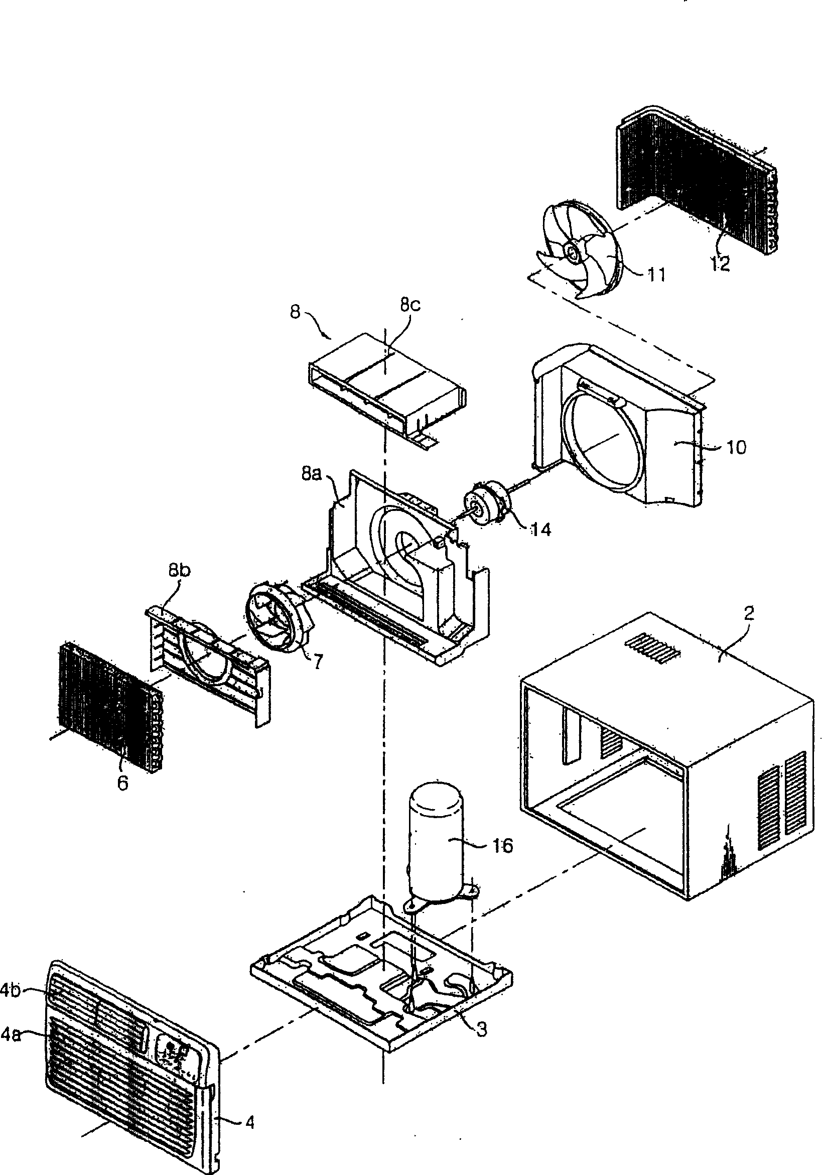
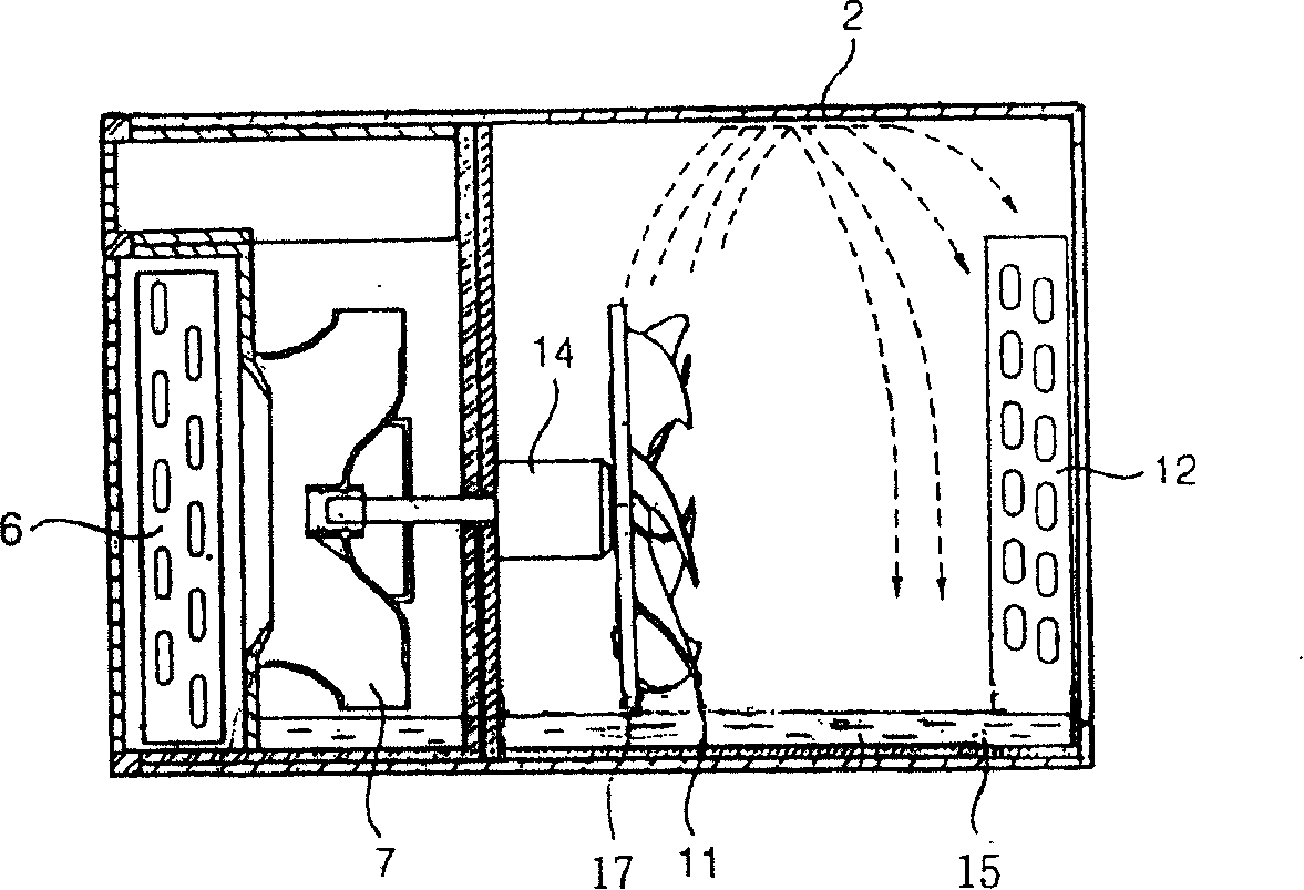
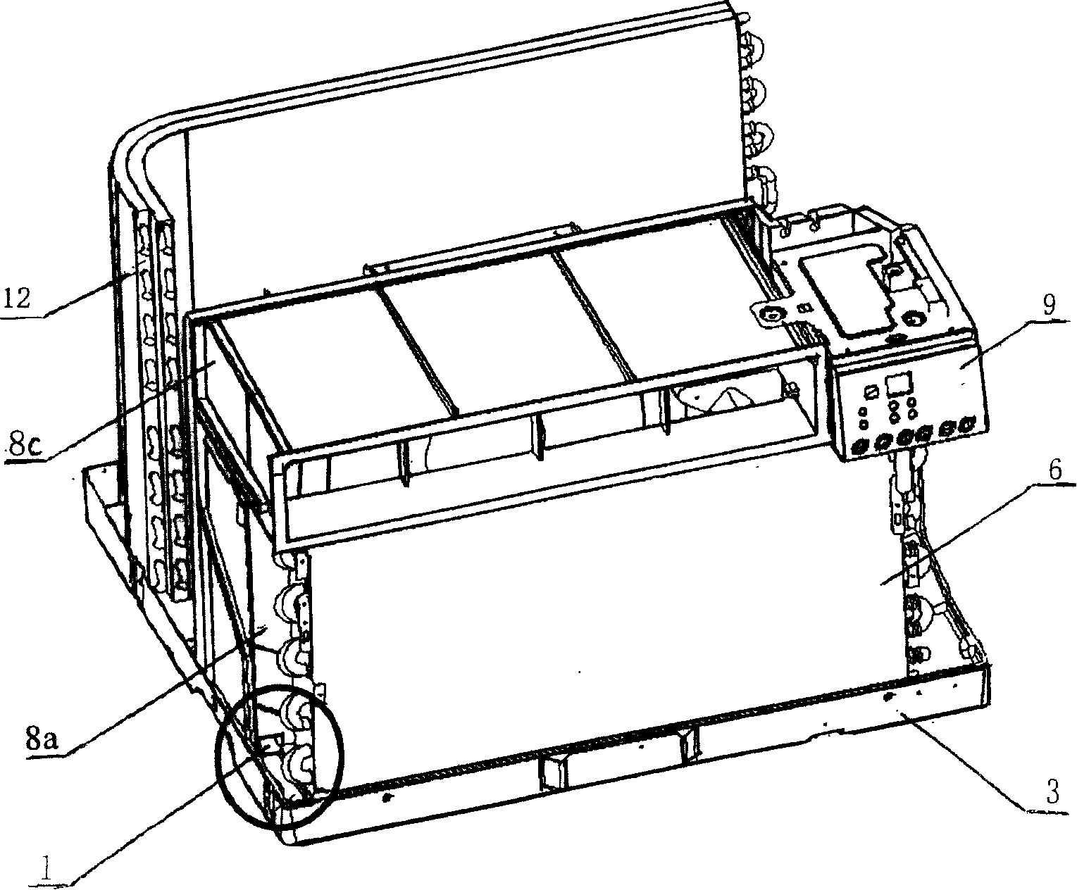
[0028] In order to further illustrate the content of the invention, technical characteristics and action principle of the present invention, give the following examples and illustrate as follows in conjunction with the accompanying drawings: figure 1 , 5 , shown in 6, the clapboard drainage hole structure of the window type air conditioner of the present invention comprises: the casing 2 that forms appearance; , there is an exhaust port 4b on the upper side; the evaporator 6 arranged behind the indoor side panel; the water receiving tray 15 arranged under the evaporator; the drainage groove 5 connected with the water receiving tray; arranged behind the evaporator, the partition and The indoor fan 7 and the fan motor 14 on the indoor air guide 8 are arranged on the chassis, and the window air conditioner is divided into the partition 8a on the indoor side and the outdoor side; the drain hole is designed on the lower part of one side of the partition of the window air condition...


PUM


Abstract

The invention relates to an air conditioner, in particular to a clapboard drain hole structure of a window air conditioner, which solves the problem of the reduction of efficiency due to the reason that the air convection of the inside and the outside of a chamber can not be cut off during the operation of the clapboard drain hole of the existing window air conditioner chamber. The structure comprises: a case forming the surface; a chassis for installing machine parts; a panel arranged in the inside of a case chamber, with a suction inlet at the lower side and a vent at the upper side; an evaporator arranged behind the panel; a water pan arranged below the evaporator; a discharge chute connected with the water pan; an indoor fan and a fan motor arranged at a clapboard behind the evaporator and an indoor air guide; a clapboard arranged at the chassis for dividing the window air conditioner into an inside and an outside; a drain hole arranged at the lower part of one side of the clapboard; a compressor arranged at the outside of the clapboard; an outdoor fan; an outdoor air guide; and a condenser arranged at the outside of the outdoor fan. The invention is characterized in that: the discharge chute below the drain hole of the clapboard is also designed with a U-shaped chute structure.

Description

technical field [0001] The invention relates to a window type air conditioner, in particular to a partition plate drain hole structure of the window type air conditioner. Background technique [0002] Existing window air conditioners such as Figure 1-4 As shown, the chassis 2 forming the exterior; the chassis 3 on which the components are installed; the panel 4 arranged inside the chassis chamber; the lower side of the panel 4 is formed with an air inlet 4a, and the upper side is provided with an exhaust port 4b; the inner side of the panel 4 is arranged in sequence Evaporator 6; indoor fan 7; indoor air guide 8 (8a, 8b, 8c); fan motor 14; partition 8a; compressor 16 is arranged outside the partition; outdoor fan 11; outdoor air guide 10; condenser 12 The chassis 3 is designed with a water tray 15; the water ring 17 of the outdoor fan 11 is rotated and installed in the water tray 15. When the air conditioner is running, the condenser 12 will release heat quickly because the...

Claims


Application Information

Patent Timeline
IPC IPC(8): F24F1/02F24F13/22
Inventor 李永辉
Owner LG ELECTRONICS (TIANJIN) APPLIANCES CO LTD
Learn More