
Method for determining the condition of a long body

A technology of extending body and state, applied in the field of determining the state of space extending body, can solve problems such as increasing the difficulty of electronic signals

Inactive Publication Date: 2008-04-30
SIEMENS AG
View PDF0 Cites 0 Cited by
  • Summary
  • Abstract
  • Description
  • Claims
  • Application Information

AI Technical Summary

Problems solved by technology

These interfering signals make it more difficult to identify the electronic signal being fed in

Method used


Image

  • Method for determining the condition of a long body
  • Method for determining the condition of a long body

Examples


Embodiment Construction

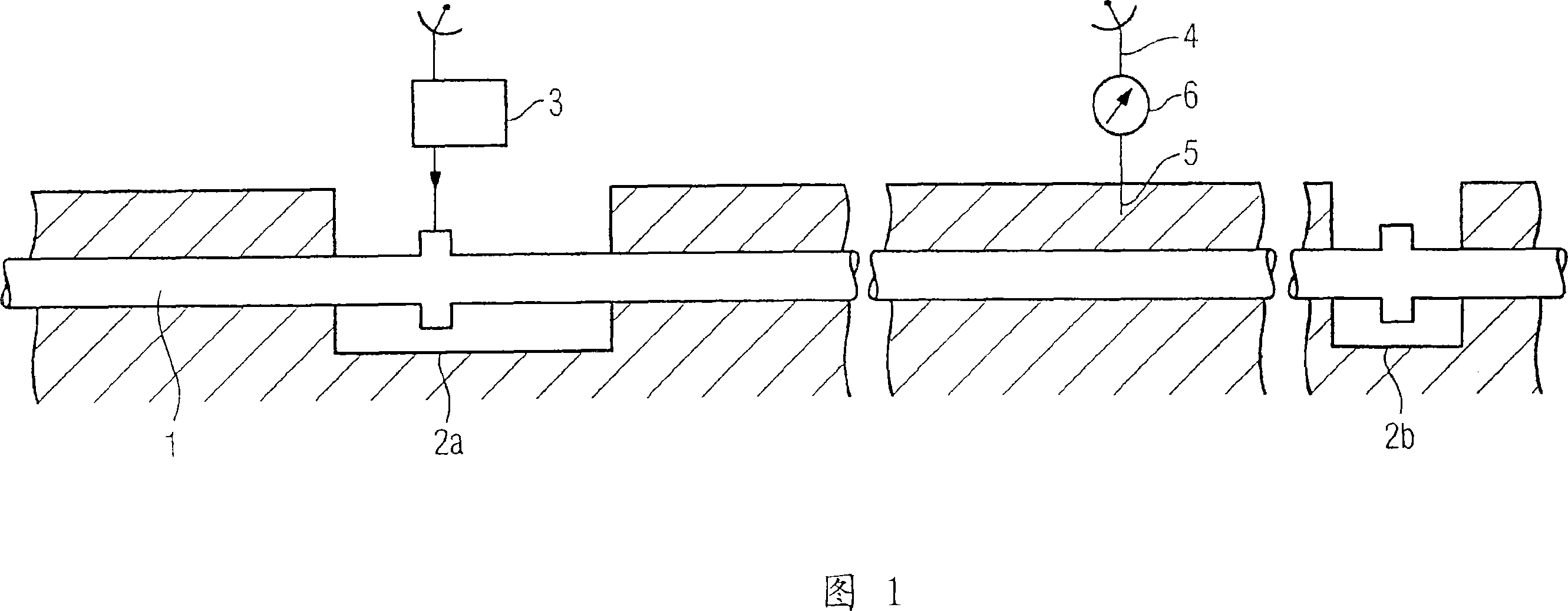
[0017] FIG. 1 shows a gas-insulated electrical conductor 1 as a spatial extension. The gas-insulated electrical conductor 1 has a tubular sheath which is provided with a corrosion-resistant coating. The housing encloses the electrical conductors placed in electrical insulation. The inside of the sheath of the gas-insulated electrical conductor 1 is filled with pressurized insulating gas. In the example shown in FIG. 1, the gas-insulated electrical conductor 1 is laid underground. However, other laying types are also possible as an alternative, for example in water or inside tunnels. The housings of the gas-insulated electrical lines can be reached at service shafts 2a, 2b. Electronic signals can be fed into the sheath of the gas-insulated electrical line 1 by means of the transmitting device 3 . The sheath of the gas-insulated electrical conductor 1 is formed, for example, from an electrically conductive material. The fed electronic signal is propagated inside the housing...


PUM


Abstract

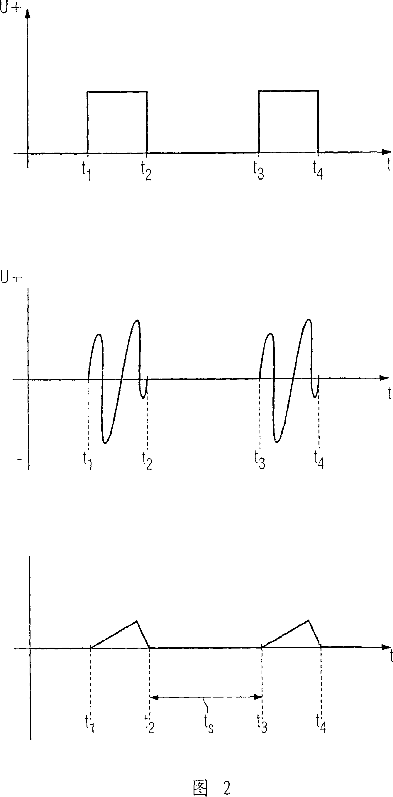
The invention relates to a long body, for example a gas-insulated electric line (1), the condition of which is tested by an electronic signal that is supplied to said body and can be received by a receiver unit. The electronic signal has a predefined duration and form. According to the method, the receiver unit receives signals, evaluates them in terms of duration and / or form and identifies said signals as the supplied signals or discards them as interference signals.

Description

technical field [0001] The invention relates to a method for determining the state of a spatial extension, wherein an electronic signal is fed into the extension and the signal can be received by a receiving device. Background technique [0002] It is known to feed an electrical signal into a pipeline and to detect this electronic signal by means of a receiver for diagnosing, for example, the anti-corrosion coating of the pipeline. Depending on the state of the anti-corrosion layer, a stronger or weaker signal or a changed waveform can be received. From the received signals, the state of the anti-corrosion coating can then be determined. [0003] In spatially extended bodies, such as long pipeline sections, the superposition of interference signals is almost unavoidable. These interfering signals make it more difficult to identify the electronic signal being fed in. Contents of the invention [0004] The technical problem to be solved by the present invention is to prov...

Claims


Application Information

Patent Timeline
Patent Type & Authority Applications(China)
IPC IPC(8): G01R31/08
CPCG01N17/02
Inventor 赫尔曼·科克
Owner SIEMENS AG
Learn More