
Method for manufacturing information display panel

一种信息显示、制造方法的技术,应用在非线性光学、仪器、光学等方向,能够解决不能进行填充、面板基板距离不能固定、飞出等问题,达到间隔均匀的效果

Inactive Publication Date: 2008-04-23
BRIDGESTONE CORP
View PDF0 Cites 1 Cited by
  • Summary
  • Abstract
  • Description
  • Claims
  • Application Information

AI Technical Summary

Problems solved by technology

[0009] However, this method has the following problem. If it is desired to fill two types of colored particles for display media with different charging polarities, although the filling of the first type of particles can be carried out without problems, when filling the second type of particles , previously filled particles fly out of the cell
[0010] In addition, this method also has the problem that when the display medium filled in the cell is moved to the next process, the filled particles fly out of the cell due to the influence of external forces such as vibration and wind.
[0011] In addition, in this method, there is such a problem that when the display medium is not only attached to the cell, but also attached to the partition wall forming the cell, the display medium is sandwiched in the gap between the substrate and the top of the partition wall when another substrate is bonded. The distance between
In order to solve this problem, it is proposed that on the substrate to be filled with the display medium, a mask with an opening corresponding to the shape of the small chamber is placed on the partition wall forming the small chamber to prevent the display medium from adhering to the partition wall, but there are still such The problem is that when the mask is removed after the display medium is filled, even the display medium filled into the small chamber comes out of the small chamber together with the mask
[0012] In addition, in this method, there is such a problem in the method of introducing charged particles into the chamber by applying a potential opposite to the polarity of the particles on the back side of the substrate. Although the filling can be performed well when the substrate has no electrodes, However, when an electrode is arranged on the substrate and the electrode exists between a component that applies a potential of opposite polarity on the back side of the substrate and the charged particles in the cell, filling cannot be performed.
The above-mentioned problems occur in the same way regardless of the method of direct spreading or the method of moving charged particles placed on a charged medium such as a photoreceptor, and the particles cannot be filled with good accuracy when electrodes are placed on the substrate.

Method used


Image

  • Method for manufacturing information display panel
  • Method for manufacturing information display panel
  • Method for manufacturing information display panel

Examples


Embodiment 1

[0160] Through the display medium filling process shown in FIG. 5 , two types of particle groups (particle group A and particle group B) having different optical reflectance and charging characteristics are continuously filled into cells of one substrate in which partition walls are formed. The particle group A and the particle group B are filled with the same volume, and the combined volume occupancy of the two particle groups is adjusted to be 25 vol% with respect to the substrate space formed by laminating the two substrates. Next, the substrate in which the particle group is filled and arranged in the cell is superimposed on another substrate, and the outer peripheral part of the substrate is bonded and sealed with an epoxy-based adhesive, and the display medium (particle group A and particle group B) is enclosed. A panel for displaying information is prepared.

Embodiment 2

[0162] Through the display medium filling process shown in FIG. 6, two types of particle groups (particle group A and particle group B) having different optical reflectance and charging characteristics are filled in the cells of the substrate with partition walls and the other cell without partition walls. A substrate chamber. The particle group A and the particle group B are filled with the same volume, and the combined volume occupancy of the two particle groups is adjusted to be 25 vol% with respect to the substrate space formed by laminating the two substrates. Next, the two substrates in which the particle groups are filled and arranged in the small chamber are superimposed on each other, and the outer peripheral parts around the substrates are bonded and sealed with an epoxy-based adhesive, and the display medium (particle group A and particle group B) is sealed to prepare information. Display panel.

Embodiment 11

[0171] Two types of display media (particle group A and particle group B) of different charging characteristics, white and black, were successively filled into cells of one substrate with partition walls according to the display medium filling process shown in FIG. 11 . First, the black display medium (group of black particles) is filled, and the ion generator (SJ-F010 produced by KEYENCE CORPORATION.) is used to remove the static electricity, and then the white display medium (group of white particles) is superimposedly filled. Table 2 below shows the results of observation and evaluation of the state after the completion of the filling step.


PUM

PropertyMeasurementUnit
particle diameteraaaaaaaaaa

Abstract

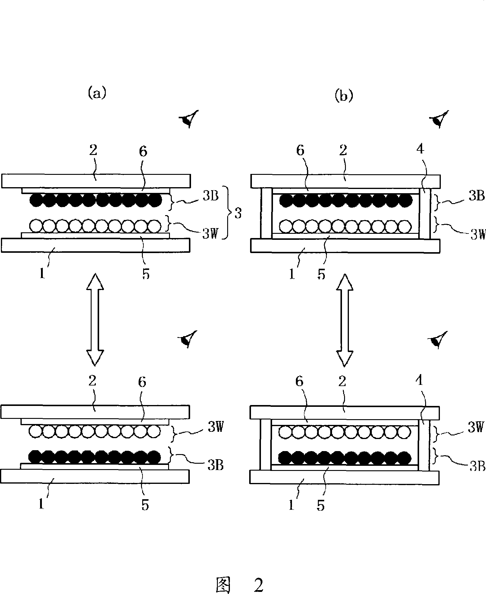
A method for manufacturing an information display panel which displays information such as an image by sealing at least one kind of display medium composed of at least one kind of particles and having an optical reflectance and a chargeability in a cell (14) formed by partitions between two substrates (1, 2) at lest one of which is transparent, applying an electric field to the display medium, and thereby moving the display medium. The method comprises a display medium placing step of placing the display medium in the cell. The display medium placing step includes a display medium charge supporting substep of supporting the charged display medium, a display medium arranging substep of arranging the supported display medium according to an electrostatic latent image, and a display medium transfer / placing substep of transferring / placing the arranged display medium into the cell.

Description

technical field [0001] The present invention relates to a manufacturing method of a panel for information display, wherein the panel for information display encloses at least one type of particles with optical properties in a cell formed by a partition wall between two opposing substrates at least one of which is transparent. The display medium has at least one or more of reflectivity and chargeability, and information such as images is displayed by applying an electric field to the display medium to move the display medium. Background technique [0002] Conventionally, as an information display device replacing a liquid crystal (LCD), an information display device using technologies such as an electrophoretic method, an electrochromatic display method, a thermal method, and a two-color particle rotation method has been proposed. [0003] Compared with LCD, these existing technologies are considered to be technologies that can be used for next-generation inexpensive informat...

Claims


Application Information

Patent Timeline
Patent Type & Authority Applications(China)
IPC IPC(8): G02F1/17G02F1/167G02F1/1679
CPCG02F1/1341G02F2001/1672G02F2001/1674G02F1/167G02F1/1681G02F1/1671G02F1/1679G02F2001/1678
Inventor 增田善友小林太一山崎博贵
Owner BRIDGESTONE CORP
Learn More