Eureka AIR delivers breakthrough ideas for toughest innovation challenges, trusted by R&D personnel around the world.

Radiation-emitting cable and a radiation-emitting element comprised therein

A technology of radiating cables and radiating elements, applied in the field of distributed antenna feeder systems, can solve the problems of time-consuming tuning, complicated devices, and complicated structures.

Inactive Publication Date: 2010-04-21
VERITEL
View PDF3 Cites 0 Cited by
  • Summary
  • Abstract
  • Description
  • Claims
  • Application Information

AI Technical Summary

Problems solved by technology

[0035] - Since the screw or conductive accessory should be screwed in / out for the purpose of adjusting the insertion position when the screw or conductive accessory is located inside the outer conductor of the coaxial cable, because of the necessity for the screw or conductive accessory to use threaded connections, Their structures are complex and time-consuming to tune;
[0036] - Installation of such a device on an already laid length of main coaxial cable is complicated, for example, in underground tunnels or other rather long foundations

Method used


Image

  • Radiation-emitting cable and a radiation-emitting element comprised therein
  • Radiation-emitting cable and a radiation-emitting element comprised therein
  • Radiation-emitting cable and a radiation-emitting element comprised therein

Examples


Embodiment Construction

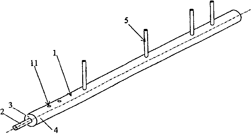
[0054] Radiating cable ( figure 1 ) contains a coaxial cable segment 1 containing an inner conductor 2 and an outer conductor 4 surrounded by a dielectric layer 3 . The device has at least two or three radiating elements 5 which can be made to tap and radiate electromagnetic energy into the surrounding space.

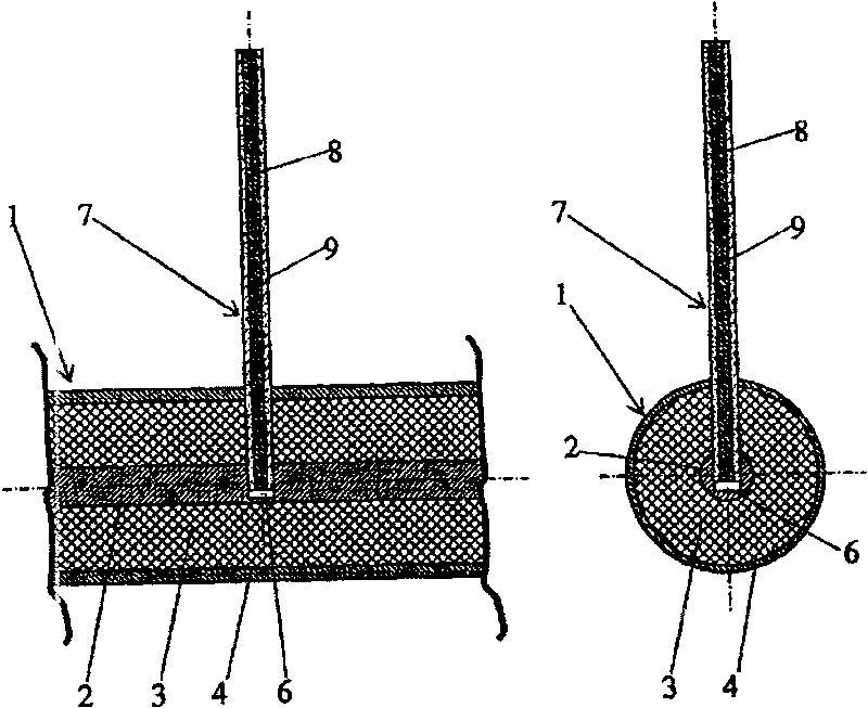
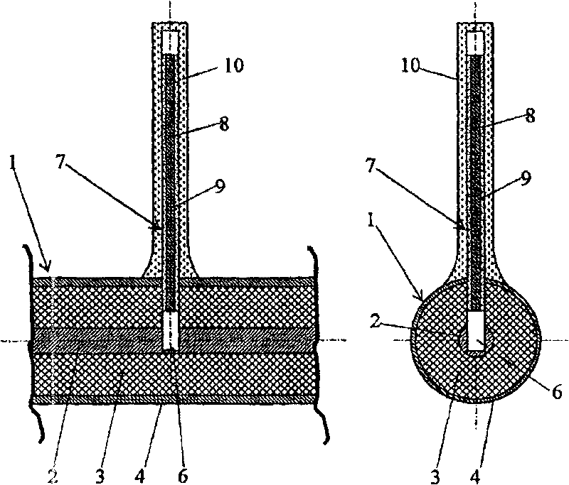
[0055] Coaxial cable segment 1 ( figure 2 , 3 ) of the outer conductor 4 , the dielectric layer 3 and the inner conductor 2 are provided with openings 6 intended to tap electromagnetic energy by means of the insert 7 . The insert 7 is made of a length of insulated wire comprising a conductor 8 and an insulator 9 .

[0056] One end of the insulated wire is installed in the opening 6 and the other end is located outside the outer conductor 4 of the coaxial cable 1, which can radiate electromagnetic energy into the surrounding space.

[0057] In order to change the electromagnetic energy tap factor, the insert 7 is tightly mounted, with the possibility of moving the i...


PUM

PropertyMeasurementUnit
diameteraaaaaaaaaa
diameteraaaaaaaaaa
diameteraaaaaaaaaa

Abstract

The inventive radiation-emitting cable comprises a coaxial cable segment (1) and at least two radiation-emitting elements (5). Said radiation-emitting element is embodied in the form of an insert. Theexternal conductor (4), dielectric layer (3) and the internal conductor of the coaxial cable segment (1) are provided with an opening which is embodied therein and used for tapping electromagnetic energy by means of said insert. The insert is made from an insulated wire segment whose one end is placed in the opening and the other end is arranged outside of the external conductor (4) of the coaxialcable segment (1) in such a way the electromagnetic energy is irradiated into environment .The electromagnetic energy tapping and irradiating device is embodied in the form of said radiation-emitting element (5).

Description

technical field [0001] The present invention relates to a radio device that can be used as a radiating element in an antenna system or as a distributed antenna feeder system for wireless access to various types of radio communications. Background technique [0002] Various types of radiating coaxial cables, known in the art, combine the properties of a radio transmission line and a long antenna. In these devices the tapping and radiating functions are performed through openings (slots) or groups of openings made in the outer conductor of the coaxial section (WO, A, 9917401), (RU , A, 2231180). [0003] Radiating cables are used in various tunnels on highways and railways, in tunnels, in underground structures such as multi-storey car parks, underground parts of large buildings, and even behind large multi-storey buildings made of reinforced concrete. In venues, they are designed to eliminate "dead zones" or shadow areas for radio communications. [0004] The cheapest and ...

Claims


Application Information

Patent Timeline
Patent Type & Authority Patents(China)
IPC IPC(8): H01P3/06H01B11/18H01Q13/18H01Q13/20
CPCH01Q13/203
Inventor M·D·布卡托夫A·A·加尔琴科夫K·V·格里申M·S·纳扎罗夫O·K·鲁任I·A·克利马绍夫A·V·舍斯托夫R·V·马尔陈科
Owner VERITEL
Why Eureka
Eureka Blog
Learn More