Eureka AIR delivers breakthrough ideas for toughest innovation challenges, trusted by R&D personnel around the world.

Divided conductor powerline with loading ice melting scheme

A wire and ice-melting technology, which is applied in the installation of electrical components and cables, overhead installation, etc., can solve the problems of large power loss, many operations, and large investment, and achieve low power consumption, simple implementation, and high safety in melting ice Effect

Inactive Publication Date: 2008-04-16
龚良贵
View PDF0 Cites 15 Cited by
  • Summary
  • Abstract
  • Description
  • Claims
  • Application Information

AI Technical Summary

Problems solved by technology

However, either the technology is too complicated, or the investment is too large, or the effect is not ideal, and they cannot be popularized and applied.
[0004] The short-circuit ice-melting method currently used on transmission lines of 220 kV and below in my country not only requires an independent ice-melting power supply and ice-melting circuit, but also requires many operations and large power losses, which seriously affects the safe operation and reliable power supply of the power grid. It is a last resort. way
However, the 500 kV and above lines cannot provide enough short-circuit capacity for ice melting at present.

Method used


Image

  • Divided conductor powerline with loading ice melting scheme

Examples


Embodiment Construction

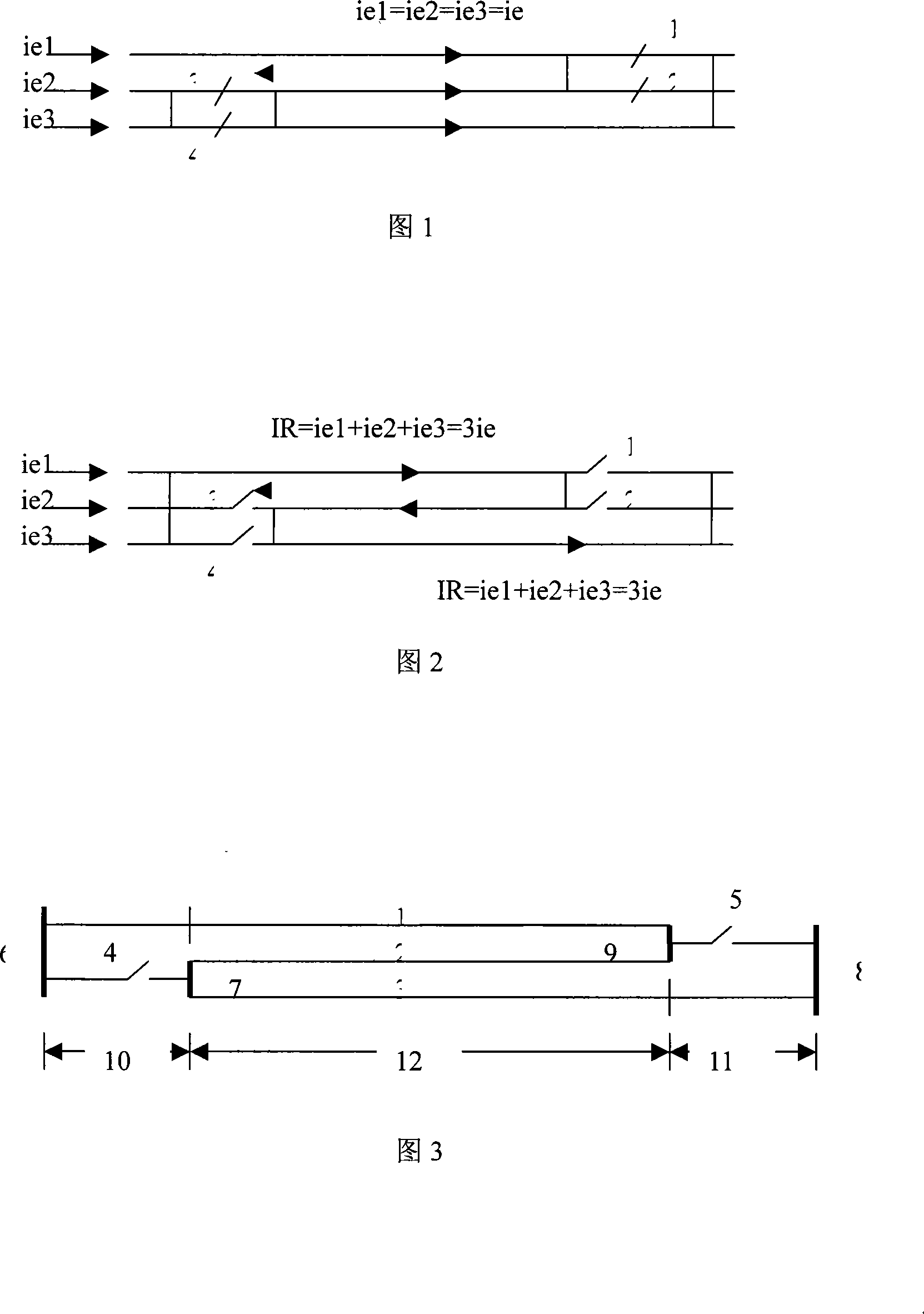
[0025] The ice-covered area of ​​the new line adopts three-split conductors, and the cross-section of the conductors is still selected according to the economic current surface density, and implemented according to Figure 3, that is, to realize ice melting under load. The ice-covered tension-resistant section of the line that has been put into operation is assembled according to the accompanying drawing 3 by modifying the wires and the metal fittings of the wires, and adding two sets of isolation switches and four sets of diversion plates to realize ice melting under load.


PUM


Abstract

The present invention discloses a load carried ice melting proposal applicable to splitting the transmission lines of a lead. The present invention adopts three-splitting lead in ice-coated tension resistance section to insulate three sub-leads of the three-splitting lead by a spacing rod so that three independent current circuits are formed. When the three-splitting lead is coated with ice, the three sub-leads are changed from parallel operation into serial operation by an isolating switch and a current guide plate which is arranged on a tension resistance tower wire jumper on two ends of ice-coated tension resistance section so that current on three sub-leads is increased to load current of three times, thereby realizing load carried ice melting for the transmission lines. The circuit principle is also applied to five-splitting lead in ice-coated tension resistance section. The current of the sub-leads is increased to load current of five times by changing the parallel operation into serial operation of the sub-leads to realize load carried ice melting. When the ice-coated tension resistance section adopts six-splitting lead, the six-splitting lead is divided into two three-splitting lead current circuits to realize load carried ice melting.

Description

technical field [0001] The invention is suitable for melting ice with load on the split wire transmission line. Background technique [0002] From the beginning of the last century to the present, power supply companies all over the world have suffered huge losses due to icing of power transmission lines, broken poles and even the collapse of power grids. For example, during the 2005 Spring Festival in the Yangtze River Basin, dozens of 500kV and 220kV lines of the Hunan Power Grid were downed and disconnected, bringing Hunan's main power grid to the brink of collapse and causing a direct economic loss of more than 70 million yuan. Indirect losses cannot be estimated. [0003] For a long time, Japan, Canada, the United States, the European Union, China and other countries with serious icing on transmission lines have spent a lot of money and manpower on preventing and controlling ice disasters on transmission lines. , Composite wire with load melting ice, insulator wire tr...

Claims


Application Information

Patent Timeline
IPC IPC(8): H02G7/16
CPCH02G7/16
Inventor 龚良贵
Owner 龚良贵
Why Eureka
Eureka Blog
Learn More