
Capacitor type electromagnetic flow meter

An electromagnetic flowmeter, capacitive technology, applied in the application of electromagnetic flowmeter to detect fluid flow, volume/mass flow generated by electromagnetic effects, measurement flow/mass flow, etc., can solve the problem of weak flow signal, large noise amplitude, signal internal blockage and other issues

Inactive Publication Date: 2008-04-16
ZHEJIANG UNIV
View PDF0 Cites 28 Cited by
  • Summary
  • Abstract
  • Description
  • Claims
  • Application Information

AI Technical Summary

Problems solved by technology

[0003] Since the flow signal generated by the capacitive electromagnetic flowmeter sensor is very weak, generally at the μV level, and the coupling capacitance formed between the electrode and the measured fluid is very small, only tens of pF, the internal resistance of the signal becomes very large. When the flow signal is coupled, strong noise will also be coupled in, and as the conductivity of the measured fluid decreases, the noise amplitude will be larger, and the very low signal-to-noise ratio makes it possible to accurately detect the flow signal from the strong noise background increased difficulty

Method used


Image

  • Capacitor type electromagnetic flow meter
  • Capacitor type electromagnetic flow meter
  • Capacitor type electromagnetic flow meter

Examples


Embodiment Construction

[0014] specific implementation plan

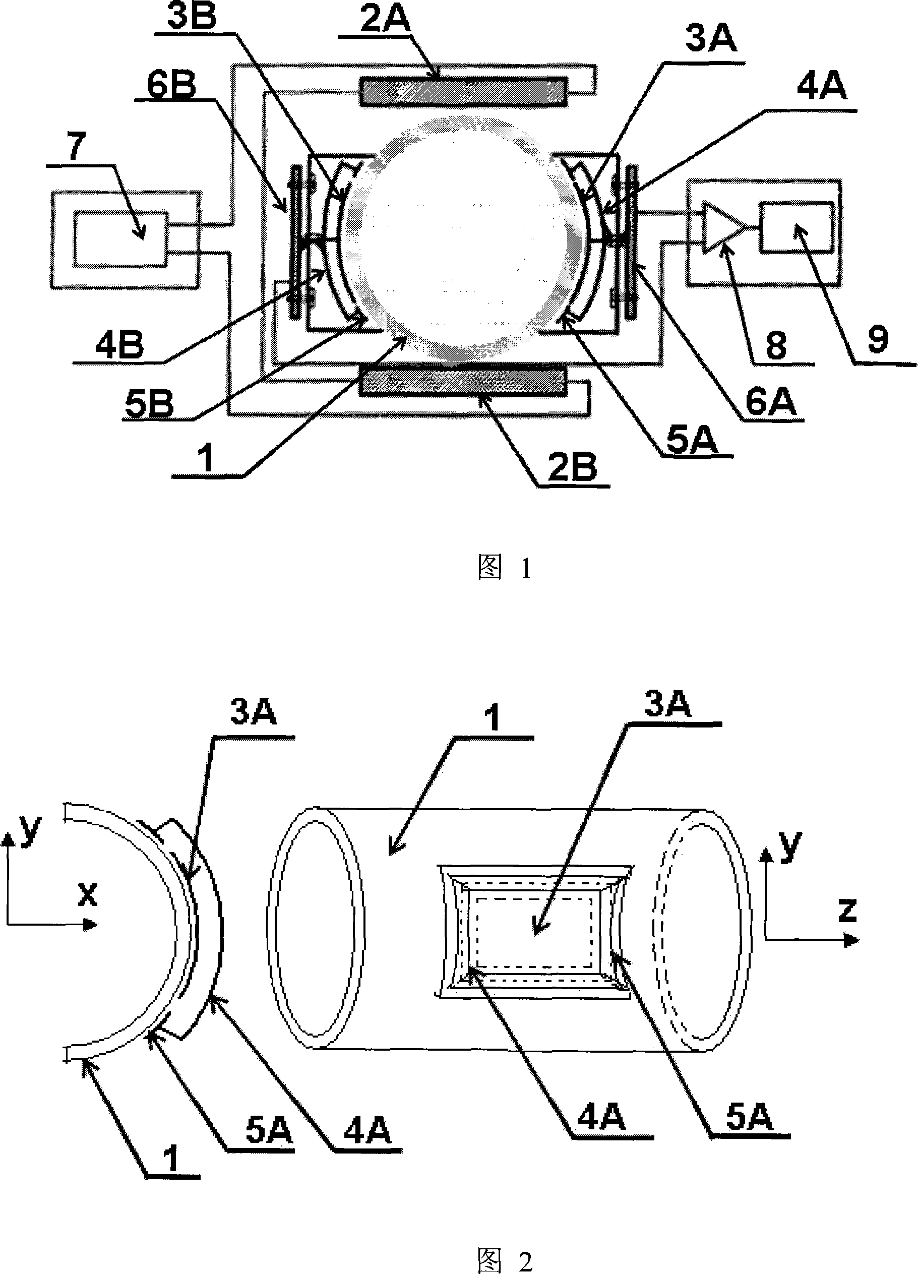
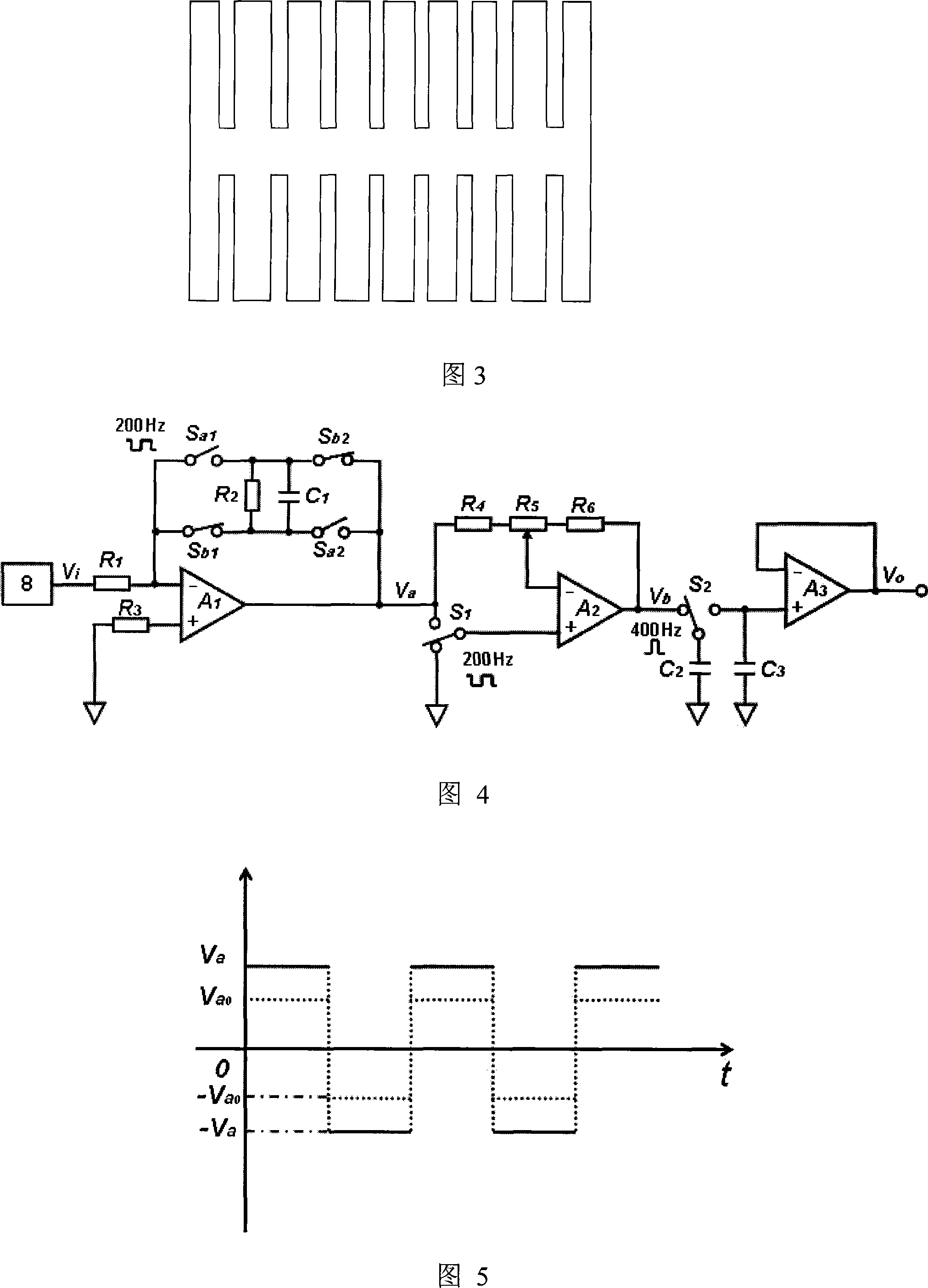
[0015] As shown in Figure 1, the capacitive electromagnetic flowmeter is provided with an upper coil 2A and a lower coil 2B connected in series on the upper and lower sides of the outer wall of the measuring tube 1, and the upper coil 2A and the lower coil 2B are connected to the excitation circuit 7. The left and right sides of the outer wall of the measuring tube 1 are provided with a left detection electrode 3A, a right detection electrode 3B, a left shield electrode 4A, a right shield electrode 4B, a left shield ring 5A, a right shield electrode 3A, and a right shield electrode. Ring 5B, the left detection electrode 3A is connected to the left preamplifier 6A, the right detection electrode 3B is connected to the right preamplifier 6B, the left preamplifier 6A and the right preamplifier 6B are connected to the differential amplifier circuit 8 and the signal processing circuit 9 phase connections.

[0016] The upper coil 2A and the lowe...


PUM


Abstract

The present invention discloses a capacitive electromagnetic flowmeter. The upper side and the lower side of the outer wall of a measuring tube are provided with an upper coil and a lower coil which are in series connection; the upper coil and the lower coil are connected with an exciting circuit; the left side and the right side of the outer wall of the measuring tube are provided with a left detecting electrode and a right detecting electrode; a left shielding electrode, a right shielding electrode, a left shielding ring and a right shielding ring are arranged outside the left detecting electrode and the right detecting electrode; the left detecting electrode is connected with a left preamplifier; the right detecting electrode is connected with a right preamplifier; the left preamplifier and the right preamplifier are connected with a differential amplifying circuit and a signal processing circuit. In the signal processing circuit of the invention, a rotary capacitance filter circuit has the effect close to an ideal square wave matched filter and can overcome the influence of strong noise, improve signal-to-noise ratio, detect feeble flow signals and convert the feeble flow signals to the direct current signals along flow changing, thereby achieving the measurement on fluid flow.

Description

technical field [0001] The invention relates to an electromagnetic flowmeter, in particular to a capacitive electromagnetic flowmeter. Background technique [0002] The electromagnetic flowmeter provides a rectangular wave excitation current to the coil to form an electromagnetic field. The fluid flowing in the measuring tube cuts the magnetic force line to generate an induced electromotive force, which is proportional to the fluid flow rate. Since the excitation current is alternating, the induced potential generated is also alternating, and its frequency is the same as that of the excitation current. A pair of comb-shaped electrode plates are set on the outer wall of the insulating measuring tube, perpendicular to the excitation coil, the electrode plates and the fluid form a capacitance with the tube wall as the medium, and the induced potential is coupled to the plate by using the coupling effect of the capacitance. The voltage difference between the two plates can be u...

Claims


Application Information

Patent Timeline
Patent Type & Authority Applications(China)
IPC IPC(8): G01F1/58G01F1/60
Inventor 王保良罗元国黄志尧李海青
Owner ZHEJIANG UNIV
Learn More