Pick-proof separating structure of a lock

A separation structure, anti-pick technology, applied in the field of anti-pick locks, to achieve the effect of strong practicability, simple structure, easy to manufacture

Inactive Publication Date: 2008-04-09
陈照林
View PDF3 Cites 7 Cited by
  • Summary
  • Abstract
  • Description
  • Claims
  • Application Information

AI Technical Summary

Problems solved by technology

But because a large amount of locks currently used do not have the function of separating and idling, this lock thief can easily use a special screwdriver to pry it open, such as the trunk locks of some cars, electric door locks of motorcycles and electric vehicles, etc. Easy to pry open by thieves

Method used


Image

  • Pick-proof separating structure of a lock
  • Pick-proof separating structure of a lock
  • Pick-proof separating structure of a lock

Examples


Embodiment Construction

[0020] The two technical solutions of the present invention will be further described in detail below in conjunction with the embodiments of the accompanying drawings.

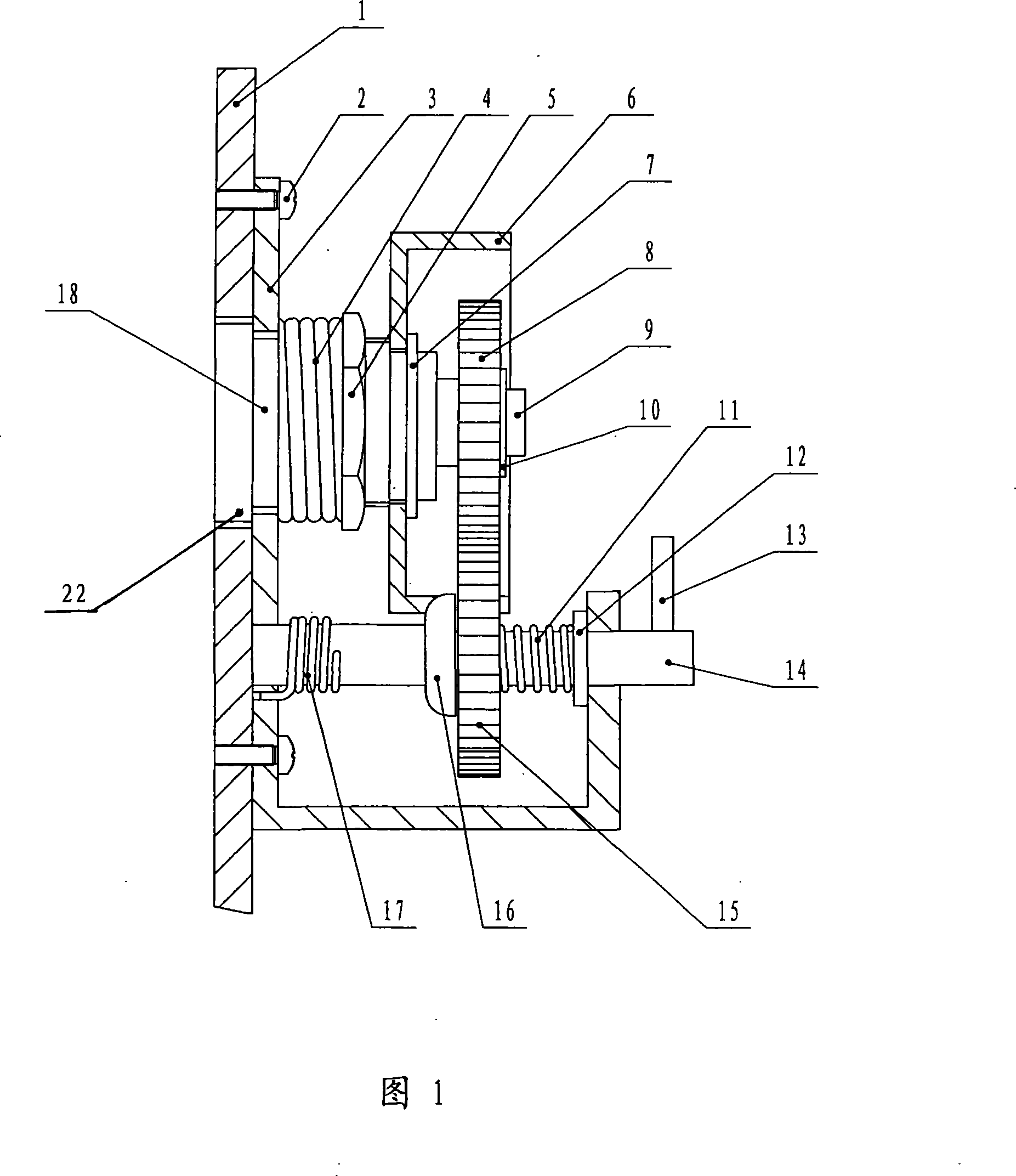
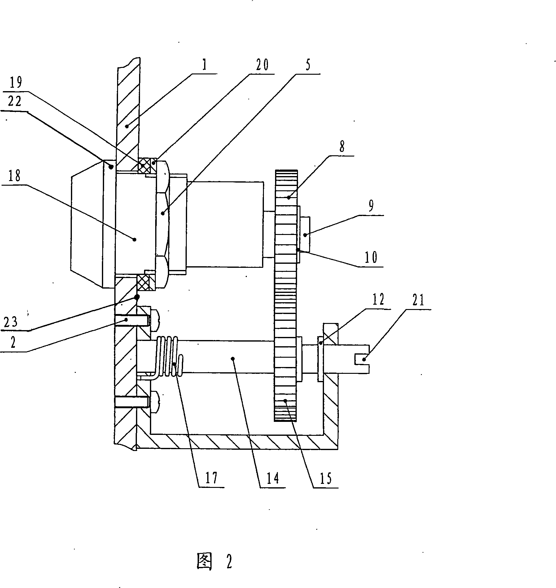
[0021] 1. Figure 1 shows an embodiment of the first solution of the present invention.

[0022] A bracket (3) is arranged, and the two ends are bent 90 degrees in the same direction, and the length and area of ​​one end are larger than the other end, and a gear shaft hole is arranged symmetrically at both ends of the bracket, and a lock body hole is arranged at the end with a larger area. Also be provided with the screw hole of fixed bracket (3); Set a gear shaft (14), a section of outer edge of gear shaft parallel axis mills a plane to install driven gear (15), return spring (11), this section reveals One section is used for the connection of the driving lever (13) outside the shaft hole, and a snap ring groove is arranged on the inner side of the joint with the bracket (3), and a separate top ring (16) is in...


PUM


Abstract

The invention relates to an anti-prizing separating structure used for a lock, which consists of a lock head, a driving gear, a driven gear and a part used for fixing the lock head. An elastic part is arranged between the lock head and the part used for fixing the lock head. When in normal use, a lock body is comparatively fixed in virtue of the elastic part; when a lock cylinder is twisted by an abnormal torque, the lock cylinder drives the lock body to turn and also drives the meshed driving and driven gears to be separated, so as to lead the torque brought to the clock cylinder for separating to fail. The invention has the advantages of simple structure, easy and simple manufacture, low cost. The lock heads installed on various bins, cases and automobiles, etc. objects all can adopt the structure of the invention, so the invention is provided with a wide application scope and a strong practicality.

Description

technical field [0001] The invention relates to the structure of a lock, in particular to an anti-pick lock capable of separating torsional force and idling. technical background [0002] All the separated anti-theft locks currently disclosed have their separated structures arranged in the lock body or in the lock cylinder. Although such designs can achieve the purpose of anti-prying, anti-technical unlocking, and even anti-drilling, these design structures are complicated, resulting in As the difficulty in the manufacturing process increases, the manufacturing cost will also increase accordingly. At present, the vast majority of thieves use the means of prying to unlock the lock, and there are not many means of using technology and electric drills to unlock the lock. Therefore, although the above-mentioned technology can prevent the lock from being opened illegally, due to cost and other reasons, the lock of this structure is not really used. not much. But because a large...

Claims


Application Information

Patent Timeline
Patent Type & Authority Applications(China)
IPC IPC(8): E05B23/00E05B17/14E05B65/00
Inventor 陈照林
Owner 陈照林
Why Eureka
Try Eureka