Cylinder injection type spark ignition internal combustion engine

A technology of spark ignition and in-cylinder injection, which is applied in spark ignition controllers, internal combustion piston engines, spark plugs, etc., to achieve the effects of good stratified combustion, promoting mixing, and suppressing attenuation

Inactive Publication Date: 2008-04-02
TOYOTA JIDOSHA KK +1
View PDF4 Cites 5 Cited by
  • Summary
  • Abstract
  • Description
  • Claims
  • Application Information

AI Technical Summary

Problems solved by technology

[0004] In the background art described above, the fuel injection valve injects fuel in a hollow conical shape. However, even if only the fuel is injected in this way, the injected fuel does not become sufficiently mixed with the intake air until it reaches the top surface of the piston or the inner diameter of the cylinder. Good combustible gas mixture, not good stratified combustion as expected

Method used


Image

  • Cylinder injection type spark ignition internal combustion engine
  • Cylinder injection type spark ignition internal combustion engine
  • Cylinder injection type spark ignition internal combustion engine

Examples


Embodiment Construction

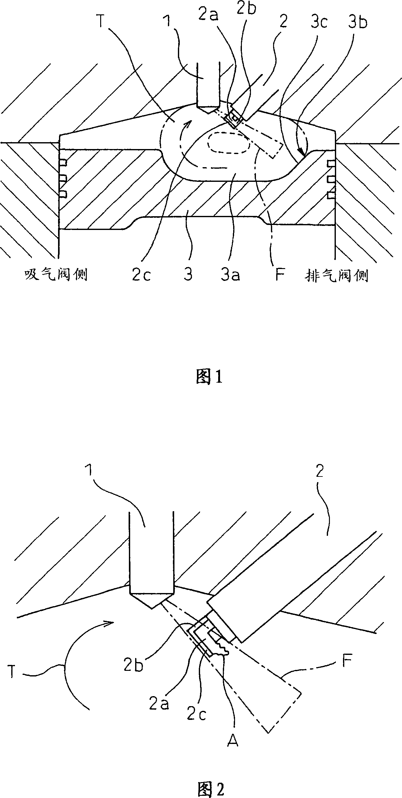
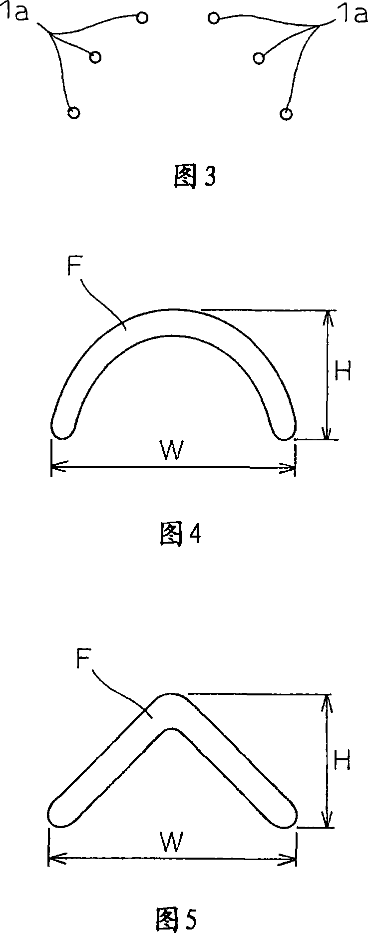
[0027] FIG. 1 is a schematic longitudinal sectional view showing an embodiment of an in-cylinder injection type spark ignition internal combustion engine according to the present invention. In the figure, 1 is a fuel injection valve for directly injecting fuel arranged at the approximate center of the upper part of the cylinder, and 2 is an ignition plug arranged near the fuel injection valve 5 on the side of the exhaust valve. This in-cylinder injection spark ignition internal combustion engine has two intake valves and two exhaust valves. Figure 1 is a cross-sectional view passing between the two intake valves and the two exhaust valves, so the intake air is not shown. valve and exhaust valve. In Fig. 1, the left side is the intake valve side, and the right side is the exhaust valve side.

[0028] 3 is a piston, and an air chamber 3a is formed on its top surface which is close to the exhaust valve side. The air chamber 3a has a smooth inner wall adapted to allow the tumble...


PUM


Abstract

The present invention provides an in-cylinder injection type spark ignition internal combustion engine, which has: a fuel injection valve that directly injects fuel into a cylinder; a spark plug that positions an ignition gap within the flight path of the fuel injected from the fuel injection valve; an air chamber , which is formed on the top surface of the piston. During stratified combustion, the fuel injection valve injects almost All the fuel is ignited by the spark plug while the fuel at the end of injection passes through the ignition gap.

Description

technical field [0001] The present invention relates to in-cylinder injection spark ignition internal combustion engines. Background technique [0002] Stratified combustion is known in which a combustible air-fuel mixture is formed only in a part of the cylinder by fuel injected in the compression stroke, and the combustible air-fuel mixture is ignited and combusted by a spark plug, thereby making it possible to ignite and burn the entire cylinder. Combustion with an air-fuel ratio leaner than the theoretical air-fuel ratio. In stratified combustion, the ignition gap of the spark plug must be located in the combustible mixture during the ignition period. Therefore, a technology has been proposed to deflect the injected fuel used to form the combustible mixture to the direction of the spark plug through the air chamber formed on the top surface of the piston. , however, the fuel injection period is therefore limited by the piston position. [0003] In order to be able to s...

Claims


Application Information

Patent Timeline
Patent Type & Authority Applications(China)
IPC IPC(8): F02B23/10F02F3/26F02M61/14F02M61/18F02P13/00
CPCF02B25/18Y02T10/125F02B2075/125Y02T10/123F02D2041/389F02B2023/106F02B2023/107F02B23/101F02B17/005Y02T10/12F02B23/10F02F3/26F02M61/18F02P13/00
Inventor 芦泽刚野村启冨野修前田薫松本圭右串田丈夫
Owner TOYOTA JIDOSHA KK
Why Eureka
Try Eureka