
Piezoelectric ignition device

An ignition device and piezoelectric technology, which are applied in the ignition, combustion ignition, and combustion methods of electric sparks, etc., can solve the problem of insufficient contact area between piezoelectric ceramics and tensioning blocks, insufficient axial thrust of piezoelectric ceramics, and parts processing. Tolerance requirements are high, to achieve the effect of simple manufacturing process, low manufacturing cost and strong output power

Inactive Publication Date: 2008-04-02
刘舜楠
View PDF2 Cites 1 Cited by
  • Summary
  • Abstract
  • Description
  • Claims
  • Application Information

AI Technical Summary

Problems solved by technology

Although it abandons the copper nut, because the tensioning block enters the shell from the side of the shell and contacts the piezoelectric ceramics, the processing tolerance of the parts is high. Once the tolerance requirements are not met, the piezoelectric ceramics will be damaged. Insufficient contact area of ​​tensioning block does not have enough axial thrust of piezoelectric ceramics, resulting in weak current

Method used


Image

  • Piezoelectric ignition device

Examples


Embodiment Construction

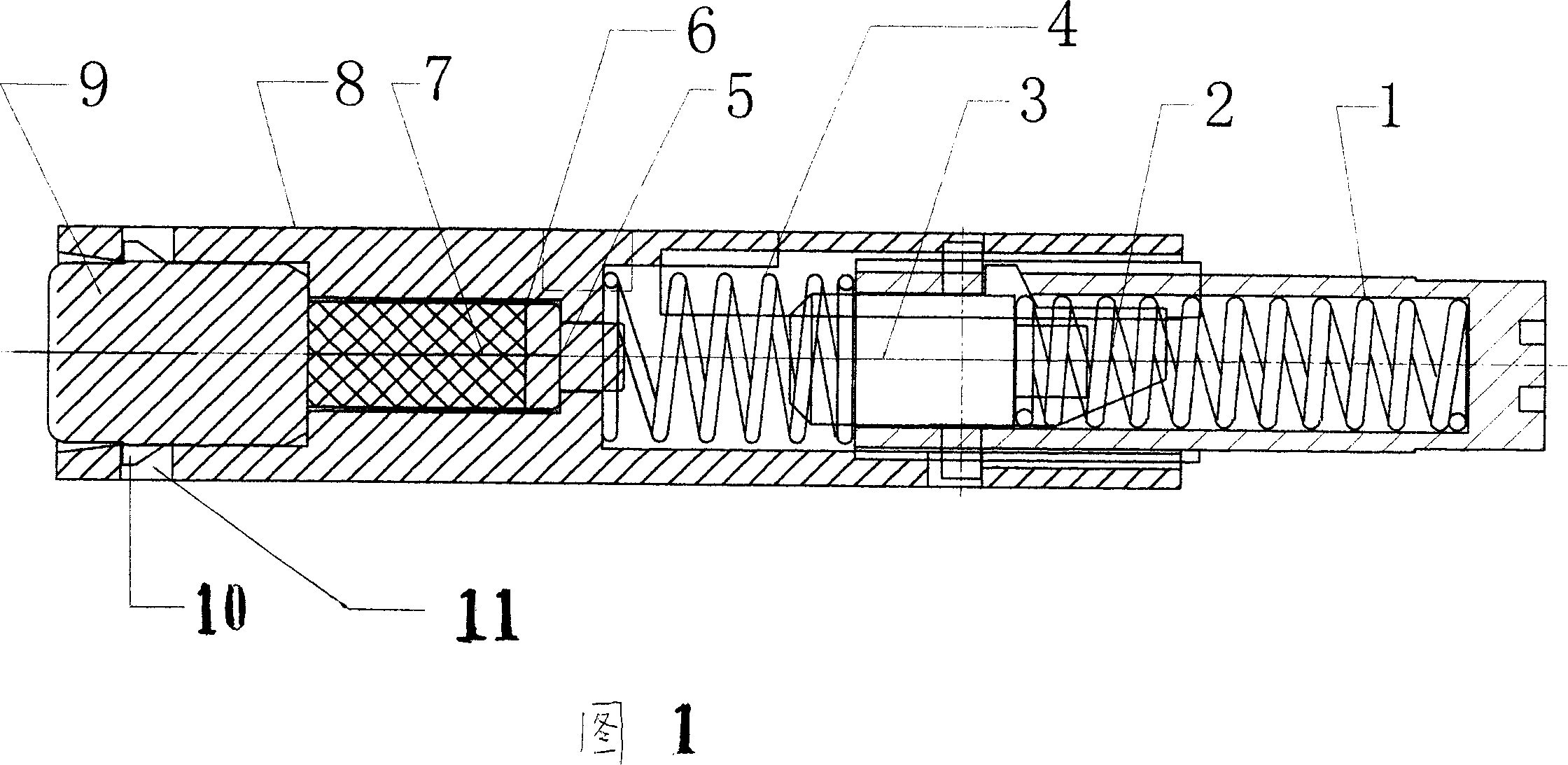
[0007] As shown in Figure 1, the present invention includes a housing 8, a button 1, a striker 2, a striker 3, a return spring 4, a contact 5, a piezoelectric ceramic 7 and a fixed pressing mechanism, which is a pad Block 9, the spacer block can be made of metal materials such as iron and copper, and the spacer block is installed in the shell with an inlaid structure.

[0008] In the figure, the cushion block 9 is in the form of a rectangular parallelepiped. A set of corresponding sides of the rectangular parallelepiped is provided with a hook 10 and a button hole 11 is provided at a corresponding position of the housing. The cuboid block 9 can be provided with hooks 10 on the two sets of corresponding sides, and correspondingly, button holes 11 are also provided on the shell. In addition, the shape of the cushion block 9 can also be a cylinder. At least three hooks are provided on the side of the cylinder in an equal arc, and a buttonhole is provided at the corresponding position...


PUM


Abstract

The invention relates to a piezoelectric ignition device for lighter; the invention aims to solve the defects that the prior piezoelectric ignition device is high in manufacturing cost and weak in electronic output. The invention adopts the following technical proposal: the piezoelectric ignition device comprises a shell, a button, an ignition spring, an ignition head, a return spring, a contact, a piezoelectric ceramics, a wire and a fixation hold down mechanism, wherein, the fixation hold down mechanism used to fix and hold down the piezoelectric ceramics is a block; the block made of pressing metallic materials is arranged in the shell by an embedded type structure. Compared with the prior piezoelectric ignition device, the invention has the advantages of low cost and strong electronic output.

Description

Technical field [0001] The invention relates to a piezoelectric ignition device for a lighter. Background technique [0002] The piezoelectric device of the lighter has a piezoelectric ceramic installed in the housing, and this piezoelectric ceramic needs to be fixed and pressed. Chinese patent CN97229695.6 discloses another fixed and pressing mechanism, which is a copper nut with an outstanding section of piezoelectric ceramic in the bottom of the shell. Because the copper nut needs to be processed with internal threads, and copper must be used in order to conduct electricity, the manufacturing cost of the product is high. Chinese patent CN97222811.X discloses a fixed pressing mechanism, which is provided at the bottom of the housing with a tension block that enters the housing from the side of the housing and contacts the piezoelectric ceramics and can generate axial thrust. Although it abandons the copper nut, because its tension block enters the shell from the side of the she...

Claims


Application Information

Patent Timeline
Patent Type & Authority Applications(China)
IPC IPC(8): F23Q3/00
Inventor 刘舜楠
Owner 刘舜楠
Learn More