
Anti-block device for horizontal centrifugal machine feeding tube

A technology for decanter centrifuges and feed pipes, applied to centrifuges, centrifuges with rotating drums, etc., can solve problems affecting the normal service life of centrifuges, achieve no jamming, eliminate jamming, reduce friction effect

Inactive Publication Date: 2008-03-26
JIANGSU HENGLIANG CENTRIFUGE MFG
View PDF0 Cites 1 Cited by
  • Summary
  • Abstract
  • Description
  • Claims
  • Application Information

AI Technical Summary

Problems solved by technology

Decanter centrifuges include casing, bearing housing, differential, drum, screw pusher, feed pipe, screw pusher is composed of main shaft and screw pusher, it is a good static and dynamic balance And its outer circular surface is equipped with a high-precision shaft-shaped part of the spiral piece, and one end of the main shaft is provided with a shaft hole for the feeding pipe to enter, and the lead of the screw pusher is distributed on the outer surface of the main shaft. The settlement area is Equal outer circle, the drying area is distributed in a conical shape. In the settling area, the main shaft is provided with a material outlet, the leftmost end of the settling area is provided with a liquid phase outlet, and the extreme end of the drying area is provided with a solid phase outlet. The main shaft passes through two Only the bearing seat is fixed on the frame, the drum is in the shape of a barrel, and is rotatably supported on the screw feeder, the differential drives the screw feeder and the drum, and the feeding tube is set on the feed of the screw feeder. During the working process, the feeding pipe is fixed on the frame, and the main shaft rotates at a high speed relative to the feeding pipe. Since the solid-liquid mixture to be separated is continuously pressed into the feeding pipe, as the solid-liquid mixture is continuously pressed, the drum The pressure of the solid-liquid mixture between the screw pusher and the screw feeder continues to increase, and the solid-liquid mixture continuously penetrates between the feed pipe and the inner wall of the main shaft. The solid particles in the solid-liquid mixture will strongly rub the feed pipe without damaging the feed pipe. It is the wear of the inner hole of the main shaft, which affects the normal service life of the centrifuge. This is a common technical problem in the existing decanter centrifuges.

Method used


Image

  • Anti-block device for horizontal centrifugal machine feeding tube

Examples


Embodiment 1

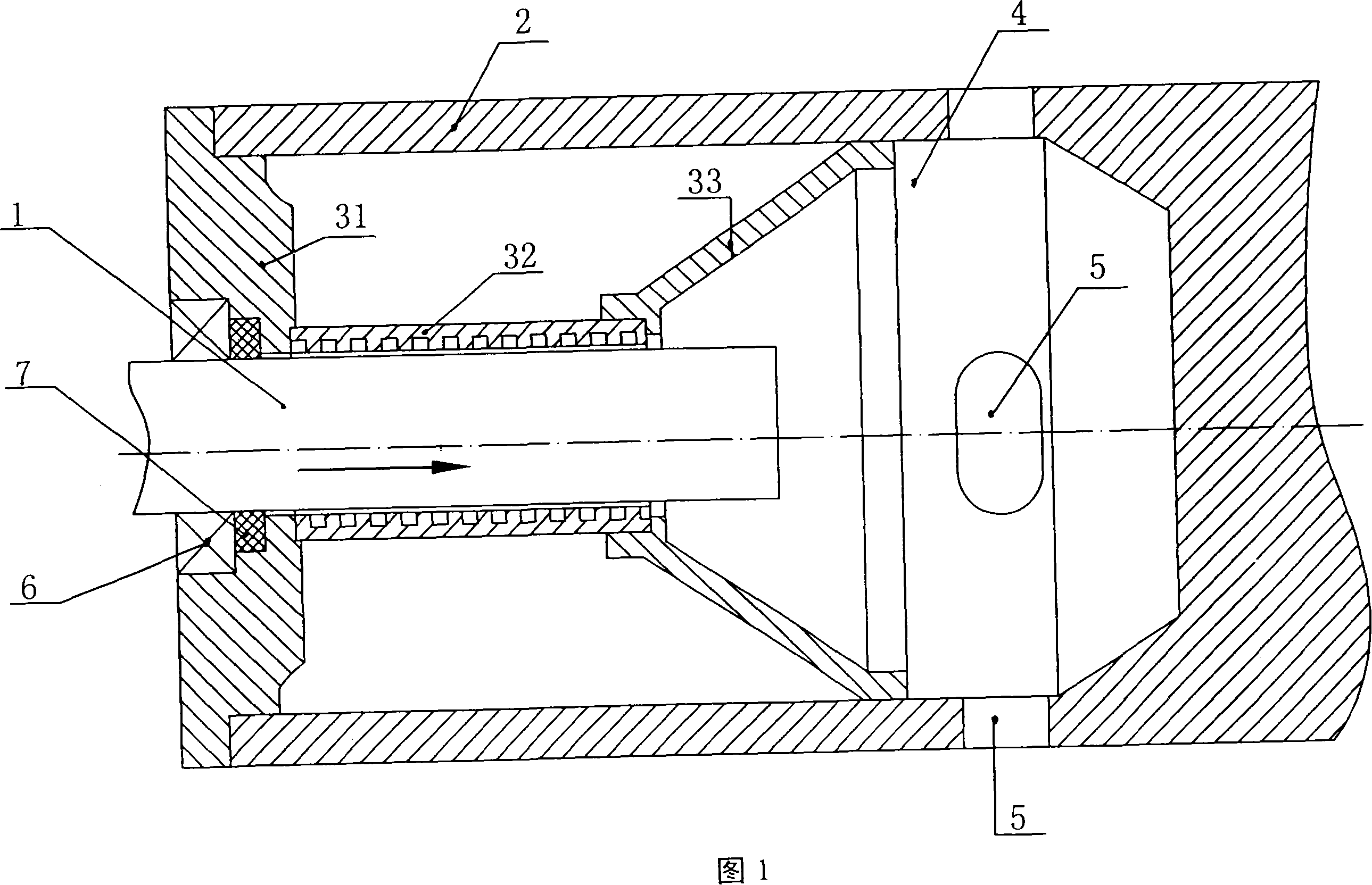
[0012] Embodiment 1: As shown in accompanying drawing 1, the feed pipe anti-jamming device of described decanter centrifuge comprises feed pipe 1, screw feeder and frame, and screw feeder is composed of main shaft 2 and screw pusher. Composed of pressing tablets, the feeding end of the main shaft 2 is provided with a shaft hole for easy installation of the feeding pipe 1, and the outer surface of the main shaft 2 is distributed with the lead of the screw pushing the pressing piece, and the main shaft 2 is fixed on the frame through two bearing seats. On the top, the feed pipe 1 is fixed on the frame, and the feed pipe 1 is installed in the inner hole of the feed end of the main shaft 2 through the anti-blocking sleeve 3. The anti-blocking sleeve 3 consists of a left end cover 31, a threaded sleeve 32, a horn sleeve 33, the horn sleeve 33 is fixed on the right end of the threaded sleeve 32, the left end cover 31 is fixed on the left end of the threaded sleeve 32, and a bearing 6...


PUM


Abstract

The present invention relates to a horizontal spiral centrifuger feeding pipe anti-blocking device. It includes feeding pipe, main shaft and machine frame. The feeding pipe is fixed on the machine frame, the feeding pipe is mounted in the inner hole of feeding end of main shaft by means of anti-blocking cover, the inner hole of the described anti-blocking cover is a screw-thread hole, and its right end is made into the horn form. Besides, said invention also provides the working principle of said anti-blocking device and its concrete operation method.

Description

technical field [0001] The invention relates to a decanter centrifuge, in particular to a feeding device of the decanter centrifuge. Background technique [0002] Decanter centrifuge is a fully enclosed equipment capable of continuous solid-liquid separation. Compared with plate-and-frame filter press and belt filter press, it has the advantages of small footprint, low capital construction cost, large processing capacity, and high separation efficiency. The effect is good, there is no need to wash with water during work, it can realize clean processing, and it is easy to operate. Decanter centrifuges include casing, bearing housing, differential, drum, screw pusher, feed pipe, screw pusher is composed of main shaft and screw pusher, it is a good static and dynamic balance And its outer circular surface is equipped with a high-precision shaft-shaped part of the spiral piece, and one end of the main shaft is provided with a shaft hole for the feeding pipe to enter, and the le...

Claims


Application Information

Patent Timeline
IPC IPC(8): B04B3/04B04B11/02
CPCB04B1/20B04B11/02B04B2001/2033
Inventor 徐志俊李章明吴锁华周建国陈小亮
Owner JIANGSU HENGLIANG CENTRIFUGE MFG
Learn More