Cooler with defroster, and refrigerator having cooler with defroster

A cooler and cooling fin technology, applied in defrosting, refrigeration and liquefaction, household refrigeration devices, etc., can solve the problems of lowering, unable to suppress surface temperature, difficult surface temperature of glass tube 12, etc.

Inactive Publication Date: 2008-03-05
PANASONIC CORP
View PDF1 Cites 5 Cited by
  • Summary
  • Abstract
  • Description
  • Claims
  • Application Information

AI Technical Summary

Problems solved by technology

[0005] However, in the above-mentioned conventional structure, there is a problem that although the distance between the glass tube heater 6 and the cooler 5 is shortened and the defrosting efficiency is improved, since the radiant heat of the glass tube heater 6 is used for defrosting, Defrost, there is a limit in further improving the defrost efficiency
[0008] At this time, there is a problem that heat is transferred to the cooling fins 10 via the plate 13 at the portion where the plate 13 is in contact with the glass tube 12 .
In this way, the surface temperature of the glass tube 12 is difficult to drop significantly, and the surface temperature of the glass tube 13 cannot be suppressed below the ignition temperature of the flammable refrigerant.

Method used


Image

  • Cooler with defroster, and refrigerator having cooler with defroster
  • Cooler with defroster, and refrigerator having cooler with defroster
  • Cooler with defroster, and refrigerator having cooler with defroster

Examples


Embodiment Construction

[0049] Hereinafter, the present invention will be described in further detail with reference to the accompanying drawings. However, the drawings are schematic diagrams, and the dimensions showing the relationship between positions are not correct. In addition, this invention is not limited to this embodiment.

[0050] (Embodiment 1)

[0051] Embodiment 1 will be described using FIGS. 1 to 6 .

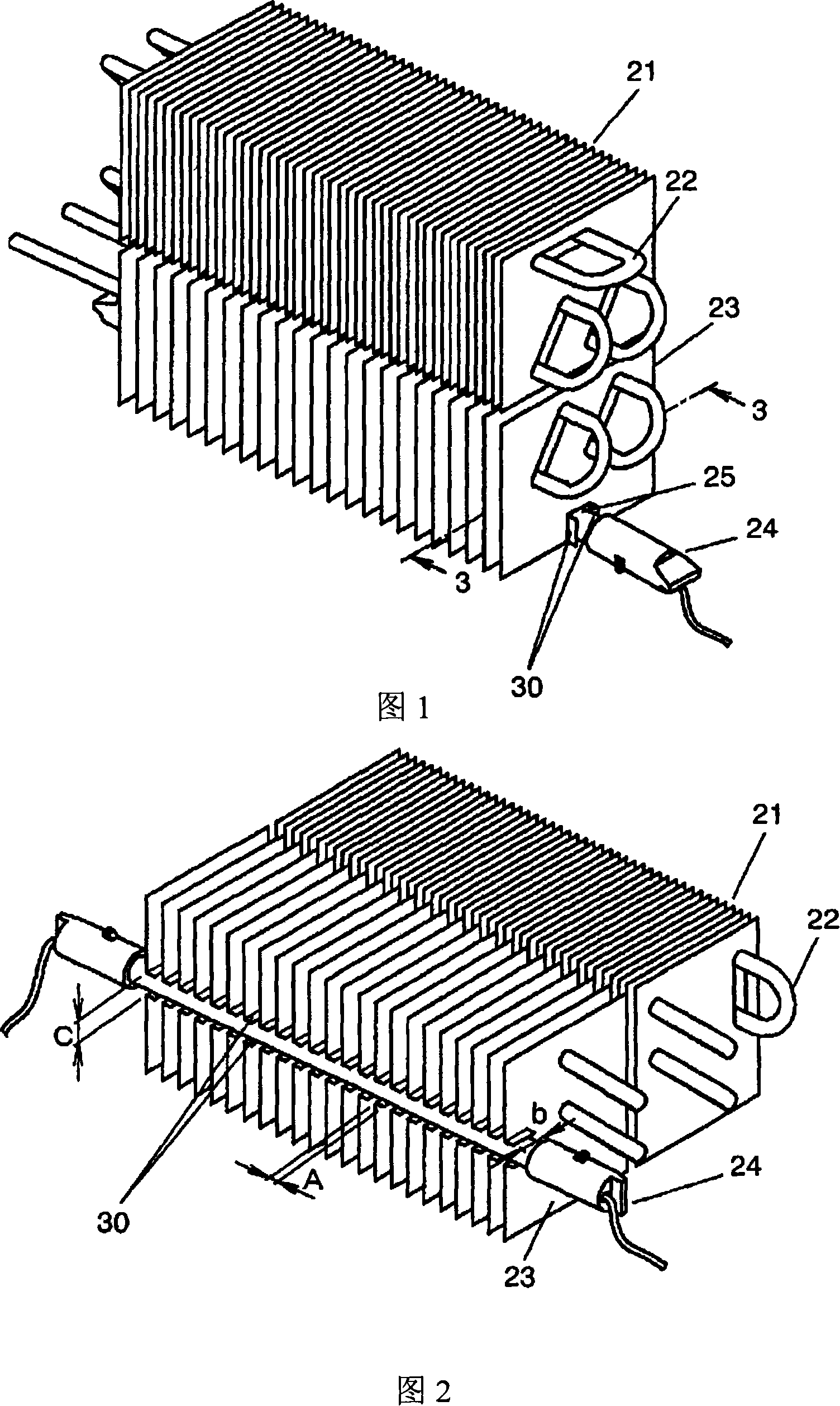
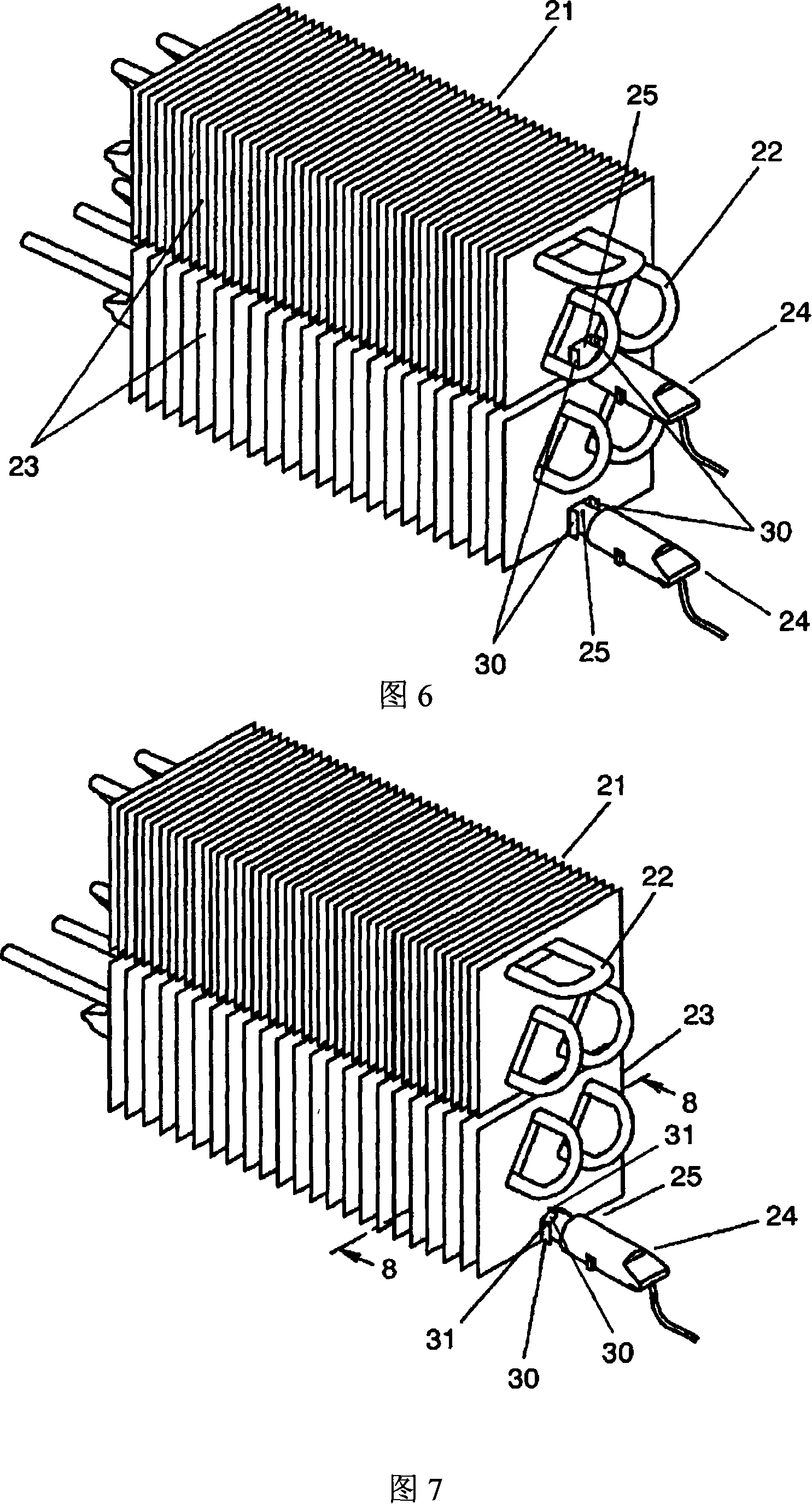
[0052] In Fig. 1, a cooler with a defrosting device (hereinafter referred to as a cooler) includes: a cooler 21 made of a plurality of cooling fins 23 and refrigerant pipes 22 passing through the cooling fins 23; Contact glass tube heater 24 as a defrosting device.

[0053] Isobutane, which is a flammable refrigerant, is sealed in the refrigerant tube 22 .

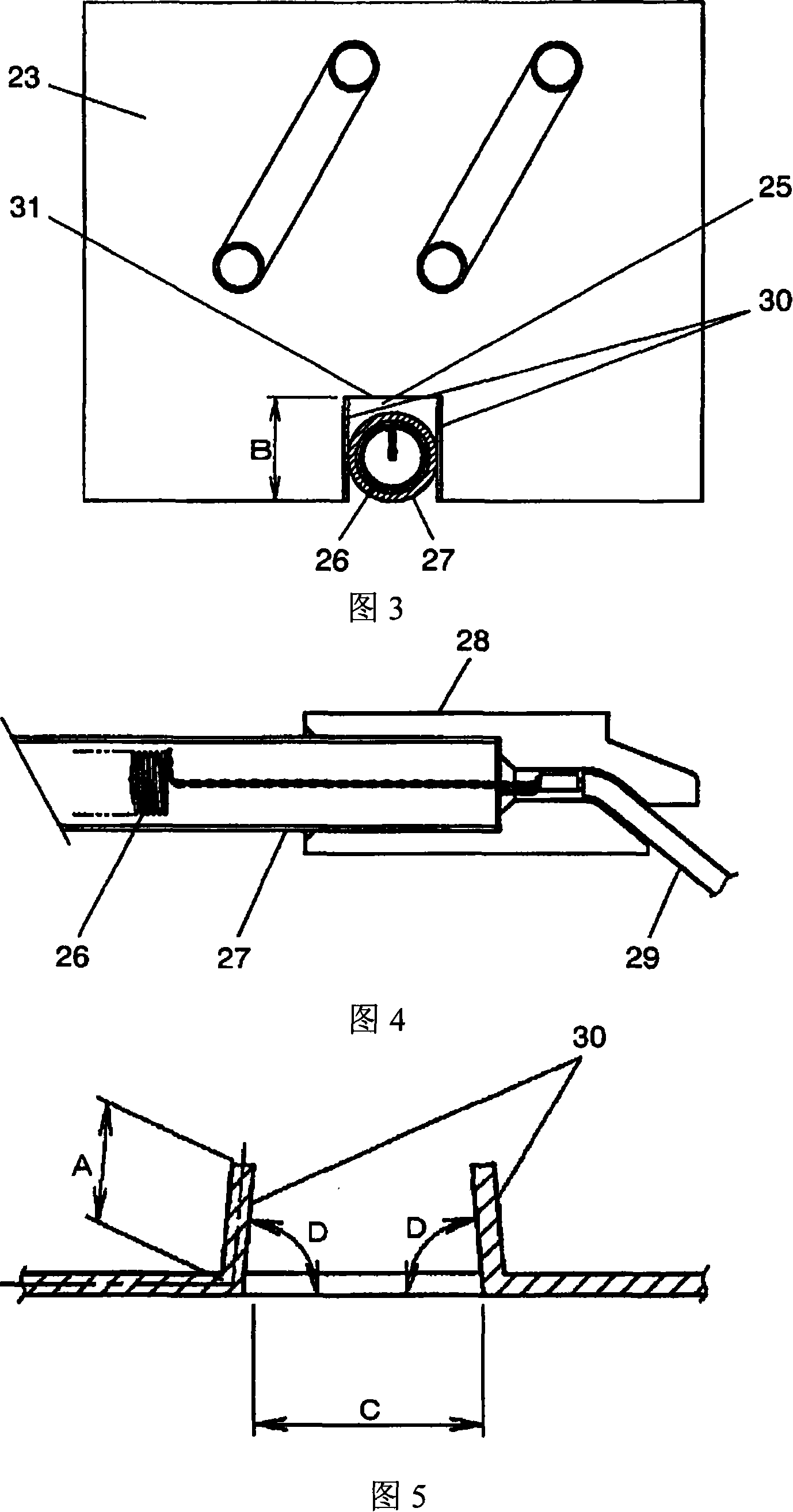
[0054] The glass tube heater 24 includes: a coiled heating wire 26 made of a metal resistor; a glass tube 27 covering the heating wire 26 ; a cover 28 covering the opening of the glass tube 27 ; and a wire 29 connected to the he...


PUM


Abstract

A notch is provided on the cooling fin, and only a bent portion is provided on the periphery of the notch in the vertical direction. The glass tube heater is inserted into the notch and the bent portion is in contact with the glass tube. The heat of the tube heater defrosts the cooler in the form of radiant heat, and the cooler can be defrosted from the side of the glass tube by heat conduction from the glass tube to the cooling fins. This provides a cooler with a defrosting device capable of improving defrosting efficiency.

Description

technical field [0001] The present invention relates to a cooler provided with a defrosting device in a refrigerator or the like, and a refrigerator provided with the cooler. Background technique [0002] The cooler of the conventional refrigerator is demonstrated. Fig. 10 is a sectional view of a main part of a conventional refrigerator. In Fig. 10, the refrigerator is provided with a freezer compartment 1 at the bottom, a freezer compartment door 2 is provided in front of the freezer compartment 1, a refrigerator compartment 3A is provided above the freezer compartment 1, and a refrigerator compartment is provided in front of the freezer compartment 3A. The door 4 is provided with a cooler 5 behind the lower part of the refrigerator body, and a glass tube heater 6 as a defrosting device is arranged in a gap opened downward at the lower part of the cooler 5, and a fan 7 is arranged on the upper part of the cooler 5. . The operation of the refrigerator configured as above...

Claims


Application Information

Patent Timeline
Patent Type & Authority Applications(China)
IPC IPC(8): F25D21/08F25B1/00
Inventor 伊藤和彦前田利树砂田正树
Owner PANASONIC CORP
Why Eureka
Try Eureka