
Laser marker for fully automatic IC material bar

A laser marking machine, fully automatic technology, used in electrical components, semiconductor/solid-state device manufacturing, circuits, etc., can solve the problems of high labor intensity of workers and low marking quality, and achieve the goal of reducing labor intensity and ensuring accuracy. Effect

Inactive Publication Date: 2008-02-20
GRAND TECH SHENZHEN
View PDF0 Cites 50 Cited by
  • Summary
  • Abstract
  • Description
  • Claims
  • Application Information

AI Technical Summary

Problems solved by technology

[0004] The purpose of this invention is to provide a new type of fully automatic marking machine for the shortcomings of existing marking machines such as low marking quality and high labor intensity.

Method used


Image

  • Laser marker for fully automatic IC material bar
  • Laser marker for fully automatic IC material bar
  • Laser marker for fully automatic IC material bar

Examples


Embodiment Construction

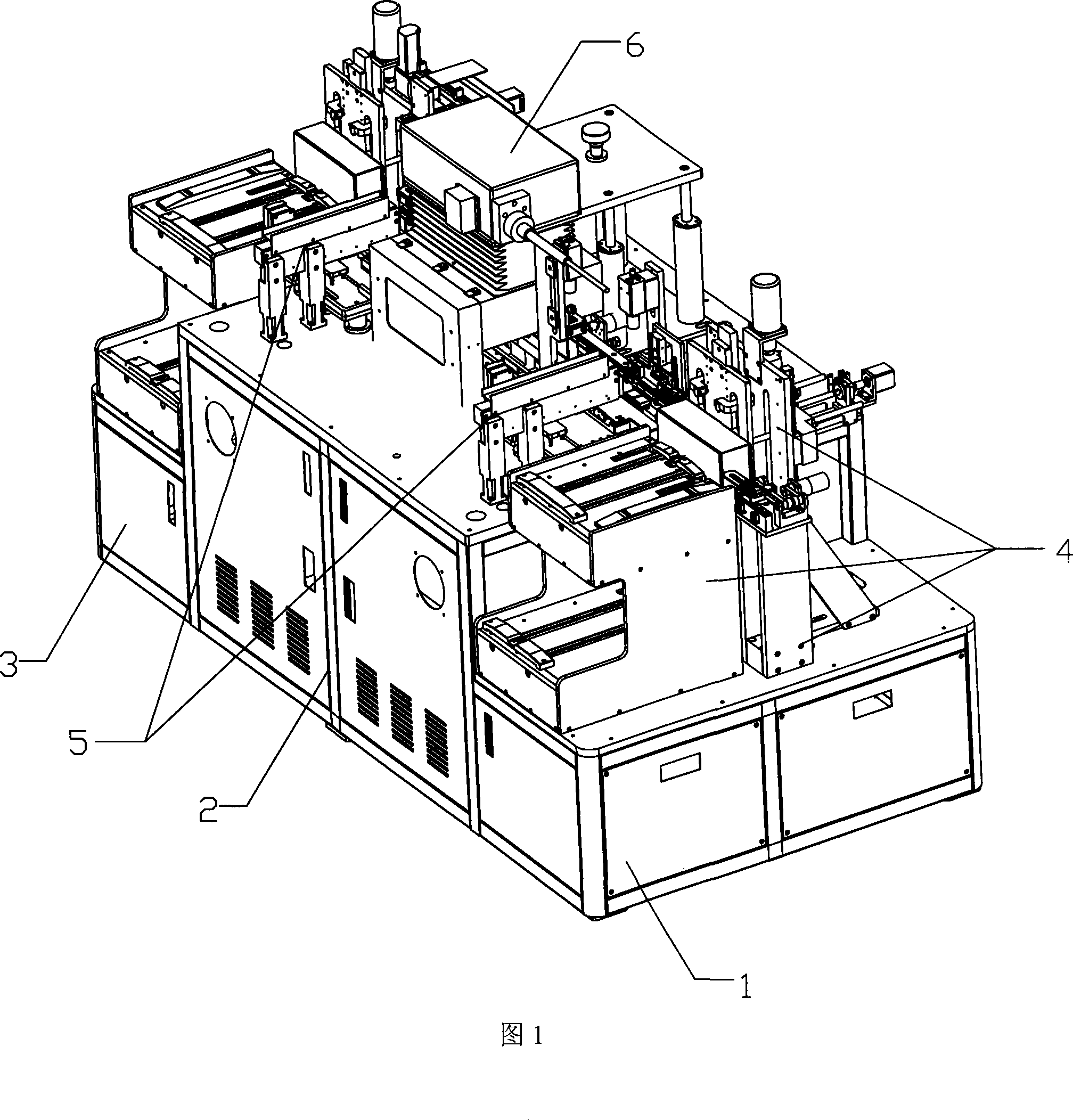
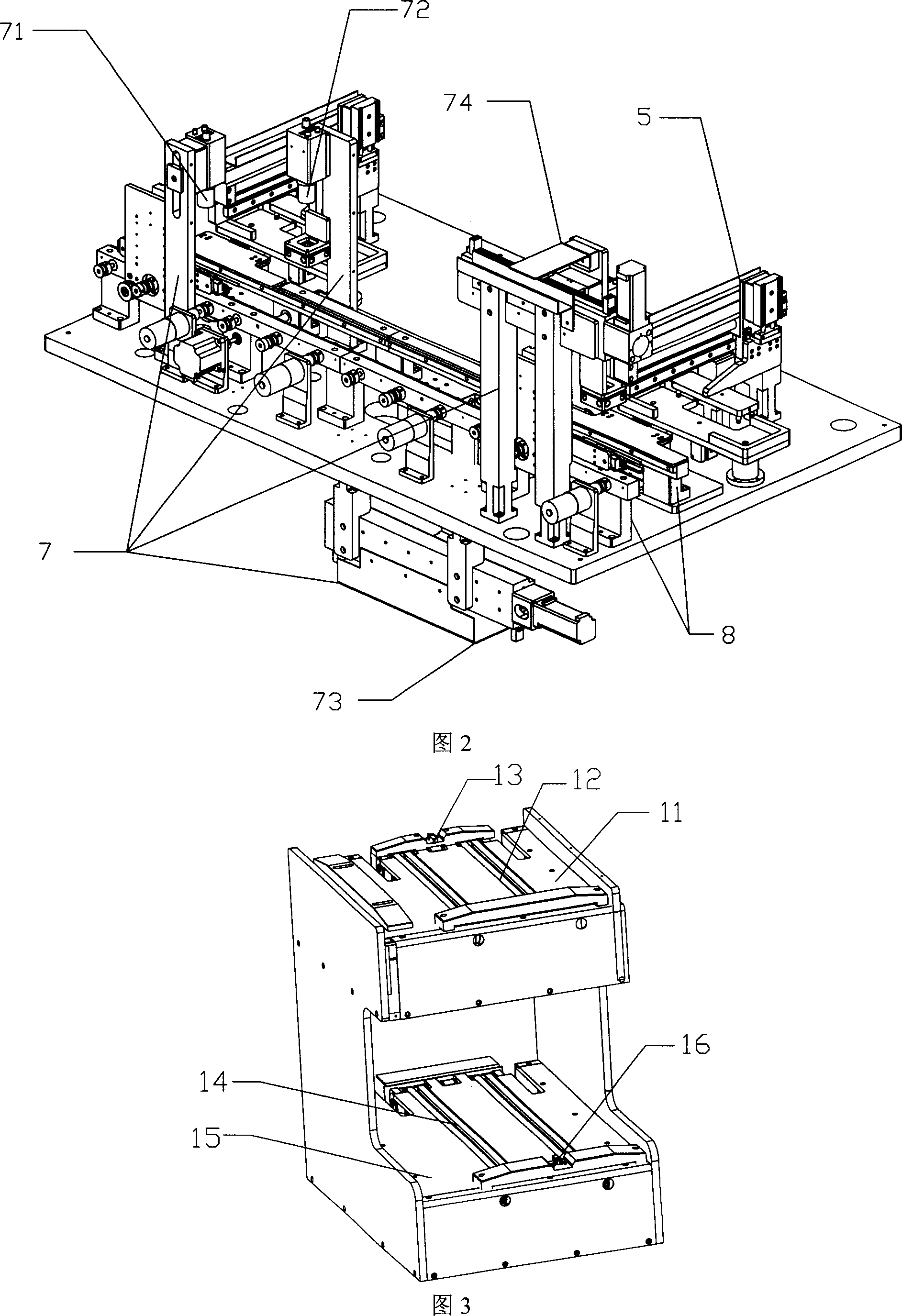
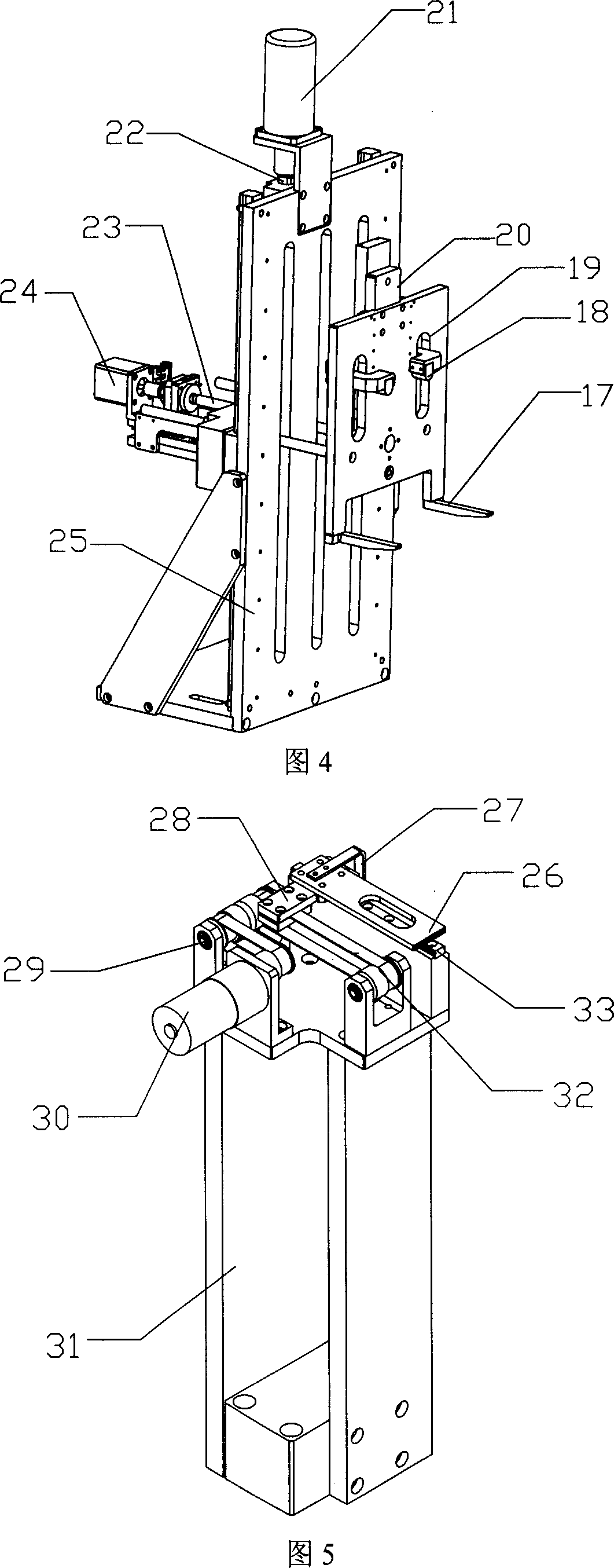
[0025] As shown in Figures 1 to 11, a specific embodiment of the present invention, a fully automatic IC bar laser marking machine, includes a body 1, a PC device 3 and an electric control system 2 are arranged inside the body, and the body 1 is provided with Controlled by the PC device 3, the loading and unloading device 4, the strip conveying device 8, the laser marking device 6, the detection system 7, and the rejecting device 5 are five major parts. The detection system 7 includes a direction detection device 71 and a batch number detection device 72. , marking position detection device 73 and post-mark quality detection device 74; The two ends of body 1 are respectively provided with loading and unloading box device 4 and unloading and boxing device, between two devices, be provided with material bar conveying device 8, between material bar The conveying lines on both sides of the conveying device 8 are successively provided with a direction detecting device 71, a batch nu...


PUM


Abstract

The utility model relates to a full automatic IC strip laser marking machine, comprising a body; wherein, a PC device and an electric control system are arranged in the body; a loading-unloading outlet device, a strip conveying device, a laser marking device, a detection system and a removing device which are controlled by the PC device are arranged on the body; the loading outlet device and the unloading outlet device are arranged on both sides of the body, and the strip conveying device is arranged between the two devices. Besides, a direction detection device, a batch number detection device, a pre-marking removing device, a laser marking device, a post-marking quality detection device and a post-marking removing device are arranged on two conveying lines of the both sides of the strip conveying device in sequence, and a marking position detection device is arranged under the laser marking device. Because the loading, conveying, detecting, removing and marking devices which are controlled by the PC device are arranged on the marking machine, the whole marking process is accurate and reasonable; meanwhile, the labor intensity can be reduced.

Description

technical field [0001] The present invention relates to a new equipment for marking IC strips. More precisely, it involves loading, testing, marking, and re-testing one by one with multi-standard strip chips, and the different detected each time. The qualified strips are immediately removed by the rejecting device there, and the marked strips are pushed into the unloading box, which is a fully automatic IC strip laser marking machine. Background technique [0002] Marking machines are widely used in the surface marking of integrated circuits in the IC industry. According to the different requirements of use, the integrated circuit boards used in the IC industry have three forms: strips (combined chips) or chips (block granular chips) and wafers. The material bar is a sheet material composed of several chips. When marking each chip on the material bar, the automatic marking is realized directly by conveying the material bar. The chip is a small piece of granular material, w...

Claims


Application Information

Patent Timeline
IPC IPC(8): H01L21/00H01L21/66
Inventor 林宜龙陈有章唐召来张松岭斐小听
Owner GRAND TECH SHENZHEN
Learn More