Air conditioner
An air conditioner and air technology, applied in the field of air conditioners, can solve the problems of high equipment cost and high operating cost
- Summary
- Abstract
- Description
- Claims
- Application Information
AI Technical Summary
Problems solved by technology
Method used
Image
Examples
Embodiment approach 1
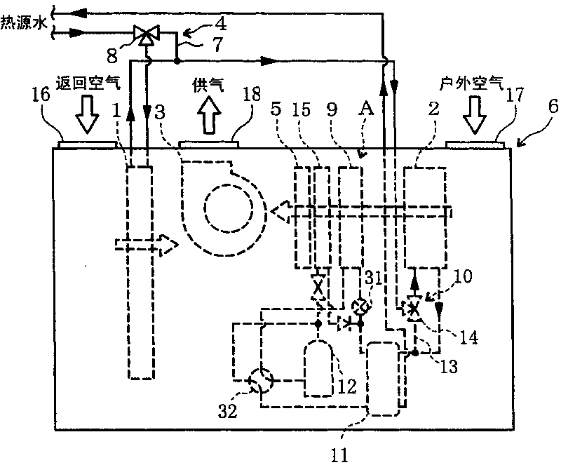
[0081] Hereinafter, the present invention will be described in detail based on the drawings showing its embodiments. figure 1 It is a schematic diagram which shows the main part structure of the air conditioner concerning Embodiment 1 of this invention.
[0082] The air conditioner according to Embodiment 1 is equipped with an outdoor air inlet 17 for taking in external outdoor air, a return air inlet 16 for taking in indoor return air, and a mixing air inlet 16 provided on one surface. The outside air and return air are supplied to the housing 6 of the air supply 18 for indoor air supply. The outdoor air inlet 17 communicates with the outside through ducts and the like, and the return air inlet 16 and the air supply port 18 communicate with the indoors through ducts and the like, respectively.
[0083] The outdoor air entering the housing 6 through the outdoor air inlet 17 and the return air entering the housing 6 through the return air inlet 16 are mixed by the suction blow...
Embodiment approach 2
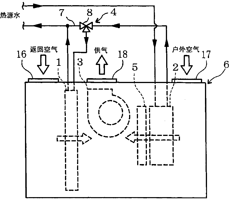
[0107] figure 2 It is a schematic diagram which shows the main part structure of the air conditioner concerning Embodiment 2 of this invention. The air conditioner according to the second embodiment has the same main part configuration as the air conditioner according to the first embodiment, but the water heat source heat pump is omitted.
[0108] The air conditioner according to Embodiment 2 includes, in the casing 6 , a return air treatment coil 1 for exchanging heat with return air, a first outdoor air treatment coil 2 for exchanging heat with outdoor air, and a first outdoor air treatment coil 2 for exchanging heat with the return air treatment coil 1 . The return air and the outdoor air heat-exchanged by the first outdoor air treatment coil 2 are mixed to supply air to the room by the suction blower 3 , and the humidifier 5 is used to humidify the outdoor air heat-exchanged by the first outdoor air treatment coil 2 . In addition, the return air treatment coil 1 is disp...
Embodiment approach 3
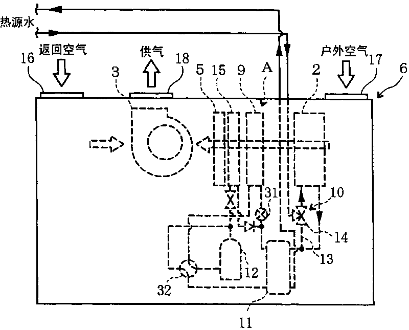
[0122] image 3 It is a schematic diagram which shows the main part structure of the air conditioner concerning Embodiment 3 of this invention. The air conditioner according to the third embodiment has the same main part configuration as the air conditioner according to the first embodiment, but the return air processing coil is omitted.
[0123] The air conditioner according to Embodiment 3 is provided in the casing 6 with: a first outdoor air treatment coil 2 for exchanging heat with outdoor air and a second outdoor air treatment coil 9 for a water heat source heat pump A; a humidifier 5 for humidifying the outdoor air; The suction type blower 3 which mixes the outdoor air processed by the 1st outdoor air processing coil 2, the 2nd outdoor air processing coil 9, and the humidifier 5, and return air, and supplies air. The return air inlet 16 is arranged to face the second outdoor air treatment coil 9 and the humidifier 5, and the blower 3 is provided therebetween. On one si...
PUM
 Abstract
Description
Claims
Application Information
 - R&D Engineer
- R&D Manager
- IP Professional
- Industry Leading Data Capabilities
- Powerful AI technology
- Patent DNA Extraction
Browse by: Latest US Patents, China's latest patents, Technical Efficacy Thesaurus, Application Domain, Technology Topic, Popular Technical Reports.
© 2024 PatSnap. All rights reserved.Legal|Privacy policy|Modern Slavery Act Transparency Statement|Sitemap|About US| Contact US: help@patsnap.com


