Convertible embossing device

A technology of printing rollers and operating positions, applied in the field of convertible embossing devices, which can solve the problems of increased reconfiguration time, incompatibility, etc., and achieve the effect of easy manufacturing and good cost-effectiveness

Inactive Publication Date: 2008-02-13
FUTURA SPA
View PDF0 Cites 3 Cited by
  • Summary
  • Abstract
  • Description
  • Claims
  • Application Information

AI Technical Summary

Problems solved by technology

The inconvenience is that it increases the time required to reconfigure the device, that is, the device is not compatible with current production standards
Also, it is necessary to have two sets of conversion tools on hand and the space required to remove one set and use the other

Method used


Image

  • Convertible embossing device
  • Convertible embossing device
  • Convertible embossing device

Examples


Embodiment Construction

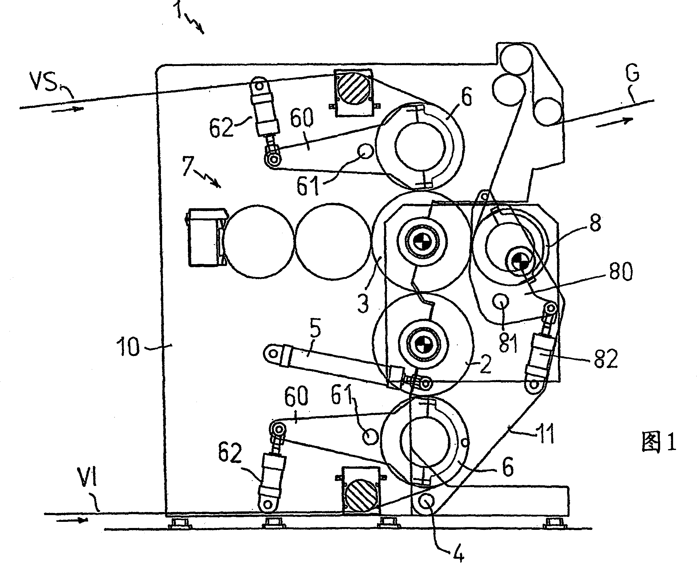
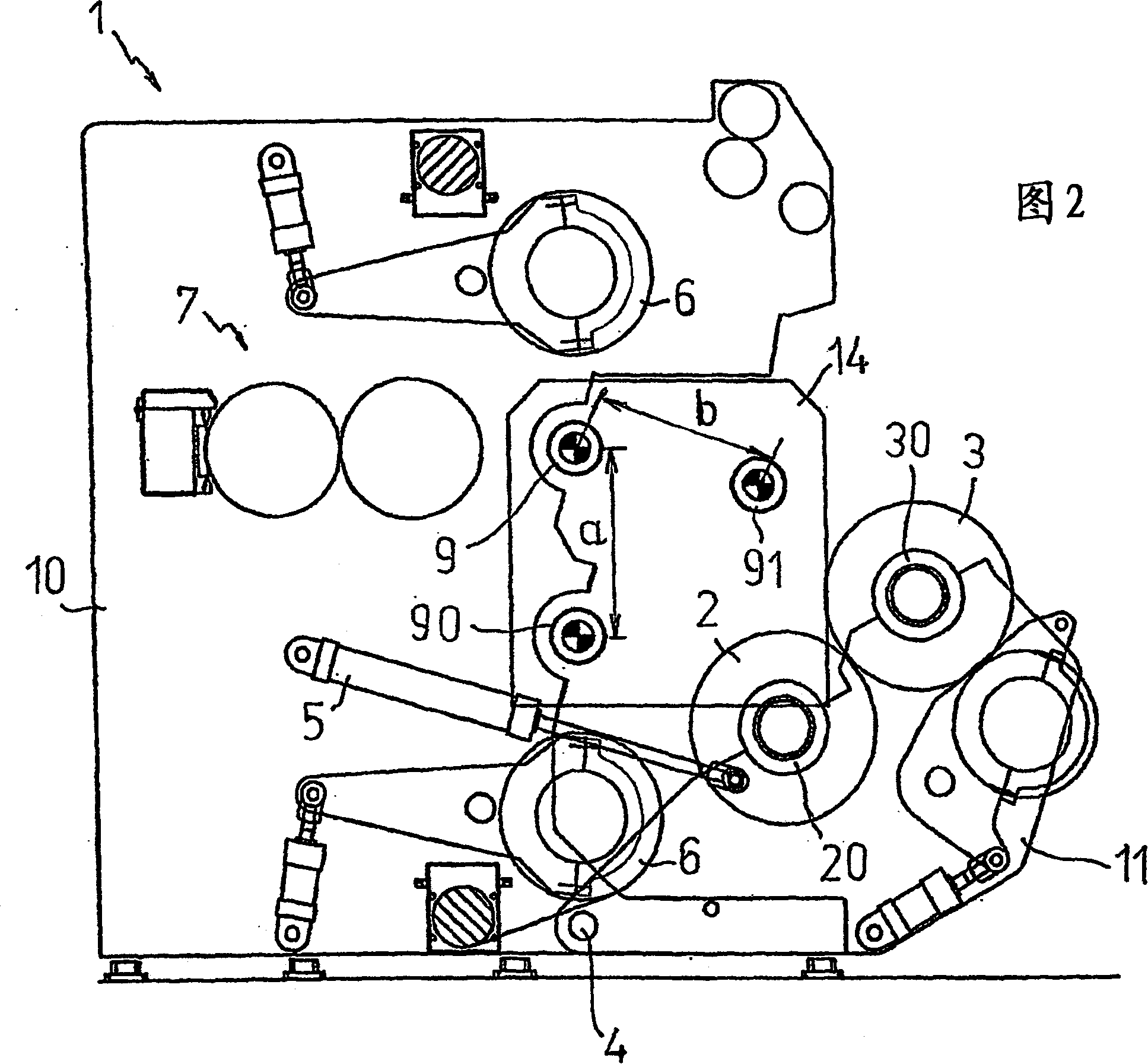
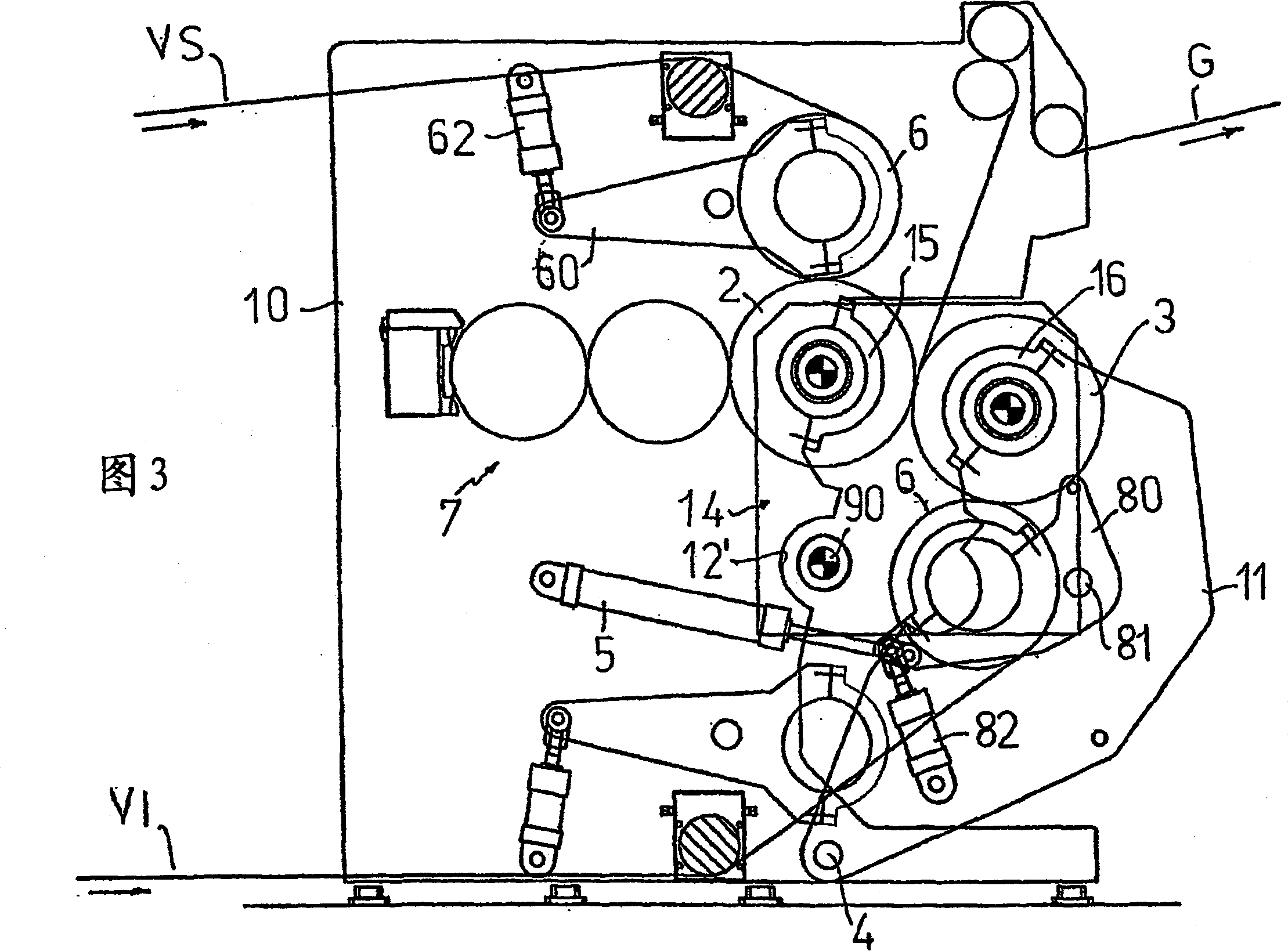
[0014] Reverting to its basic structure and referring to the illustrations in the drawings, the switchable embossing device of the present invention includes a structure 1 having two fixed sides 10, with two movable sides 11 hinged to the two fixed sides 10 on. Each of the fixed side portions 10 has an outer surface EF and an inner surface IF, and the inner surface IF faces the corresponding movable side portion 11. Similarly, each movable side portion 11 has an outer surface EM and an inner surface IM, and the inner surface (1M) faces the related fixed side portion 10. The inner surface IF of each fixed side portion 10 has two circular arc-shaped notches 12, 12', one notch 12 is set slightly higher, and the other notch 12' is set slightly lower. The inner surface IM of each movable side portion 11 has two similar notches 13, 13', and these notches are also arc-shaped. To be better described in detail below, the notches 12, 12', 13, 13' provided in the inner surfaces IF, IM of the...


PUM


Abstract

A switchable embossing device comprising a structure (1) having two fixed sides (10) and two movable sides (11) with respective outer surfaces (EF, EM) and Inner surfaces (IF, IM), and correspondingly provided with two upper notches (12, 13) and two lower notches (12', 13') on the relevant inner surfaces (IF, IM), these notches In the shape of a circular arc, it is used to support the end flanges (20, 30) of the two embossing rollers (2, 3) perpendicular to the sides (10, 11) of the above-mentioned structure (1), wherein the movable side (11) engages on the stationary side (10) and connects to the corresponding operating mechanism (5). In the first operating position, the movable side (11) is close to the fixed side (10) and the corresponding upper and lower notches (12, 12', 13, 13') act as the rollers (2, 3 ) flanges (20, 30) define two pairs of circular seats, while in the second operating position the movable side (11) is at a distance from the fixed side (10), and said side (10) and The upper notches (12, 13) of (11) each define two pairs of circles for the flanges (20, 30) of said rollers (2, 3) by cooperating with corresponding semicircular closing flanges (15, 16). shaped support.

Description

Technical field [0001] The invention relates to a switchable embossing device. Background technique [0002] As we all know, embossing is a mechanical process that transfers multiple patterns to easily deformable materials, such as roll paper or "laminated" paper. To this end, the material to be embossed passes through an embossing machine, which includes a pair of counter-rotating steel rollers and a pair of corresponding pressure rollers, the steel rollers basically having point-like protrusions. In so-called "nested" embossing, the protrusions on the rollers of the calender correspond to the recesses defined by protrusions on other rollers during manufacturing. In the case of so-called "tip-to-tip" type embossing, the protrusions on the rollers always correspond to the protrusions on the other rollers during manufacturing. In order to change from one type of embossing to another type of embossing, it is necessary to stop the manufacturing work every time, and rebuild the devic...

Claims


Application Information

Patent Timeline
Patent Type & Authority Applications(China)
IPC IPC(8): B31F1/07
CPCB31F2201/0753B31F1/07B31F2201/0764B31F2201/0766B31F2201/0782B31F2201/0776Y10T156/1737
Inventor P·卡特利
Owner FUTURA SPA
Why Eureka
Try Eureka