Sealing structure of single-stage single-suction centrifugal pump for chemical procedure

A technology of sealing structure and centrifugal pump, which is applied to parts, pumps and pump elements of pumping devices for elastic fluids. It can solve the problems of high specific pressure on the end face, shortened life, wear of friction pairs, etc., and achieve medium pressure reduction. Effects of small size, extended life, and reduced wear

Inactive Publication Date: 2008-02-13
上海开利制泵有限公司
View PDF0 Cites 2 Cited by
  • Summary
  • Abstract
  • Description
  • Claims
  • Application Information

AI Technical Summary

Problems solved by technology

Take hot water as an example: on the one hand, when delivering hot water, the working pressure can reach up to 4Mpa (at 250°C), and the pressure limit that the existing mechanical seal can withstand is generally below 2.5Mpa, so there is no pressure in the sealing chamber 3 It is not acceptable to set any auxiliary seal; on the other hand, due to the high pressure in the seal chamber, the specific pressure of the end face of the mechanical seal 4 is very high, resulting in increased wear of the friction pair, even if the mechanical seal 4 can withstand the pressure from the pump chamber 6, Its lifespan is also greatly shortened

Method used


Image

  • Sealing structure of single-stage single-suction centrifugal pump for chemical procedure
  • Sealing structure of single-stage single-suction centrifugal pump for chemical procedure

Examples


Embodiment Construction

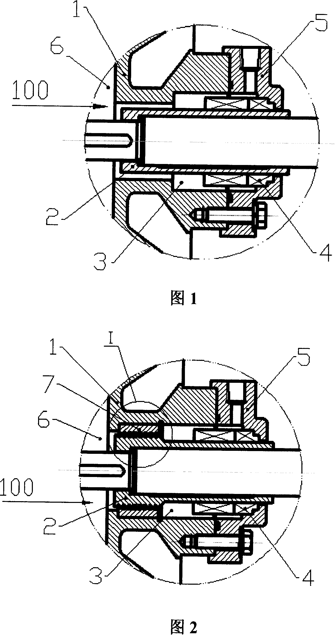
[0010] Below in conjunction with accompanying drawing and specific embodiment the present invention is described in further detail:

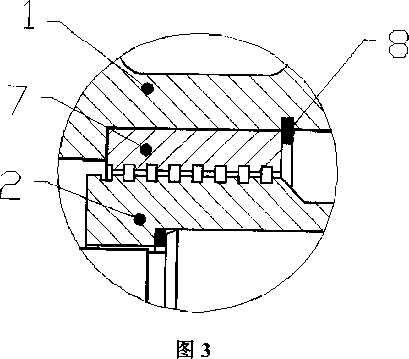
[0011] It can be seen from Fig. 2 and Fig. 3 that the present invention includes: pump cover 1, shaft sleeve 2, seal chamber 3, mechanical seal 4, mechanical seal gland 5, pump chamber 6; also includes a screw seal 7; said screw seal One end of 7 is connected with the pump cover 1 and the sealing chamber 3, and the other end of the screw seal 7 is connected with the pump chamber 6;

[0012] A hole retaining ring 8 for fixing the screw seal is arranged at the junction of the pump cover 1 , the sealing chamber 3 and one end of the screw seal 7 .

[0013] Chemical process pumps transport a wide range of media, and their working environments are also different. Some working environments have high temperature and high pipeline pressure.

[0014] In order to make the mechanical seal withstand the pressure from the pump cavity and prolong the service ...


PUM


Abstract

The invention relates to a seal structure of a single-stage and single-suction chemical process centrifugal pump, and comprises a pump cover (1), a shaft sleeve (2), a seal chamber (3), a mechanical seal (4), a mechanical seal cover (5), and a pump chamber (6), as well as a spiral seal (7). One end of the spiral seal (7) is connected to the pump cover (1) and the seal chamber (3), while the other end of the spiral seal (7) is connected to the pump chamber (6). The beneficial effect of the invention is that the medium pressure entering the seal chamber is greatly reduced due to the pumping function of the spiral seal; thus, a general mechanical seal can be used to reduce the cost; on the other hand, the specific pressure of an end surface of the mechanical seal can be reduced, and abrasion of a friction pair is reduced, so as to prolong the usable life of the mechanical seal.

Description

technical field [0001] The invention relates to a single-stage single-suction chemical process centrifugal pump, in particular to a sealing structure in the single-stage single-suction chemical process centrifugal pump. Background technique [0002] It can be seen from FIG. 1 that in the existing single-stage single-suction centrifugal pump, the sealing chamber 3 is a cavity surrounded by the pump cover 1 , the shaft sleeve 2 , the mechanical seal 4 and the mechanical seal gland 5 . When the shaft seal adopts a mechanical seal, there is no auxiliary seal in the sealing chamber 3, which is feasible when the working pressure of the pipeline is relatively low; but when the working pressure of the pipeline is relatively high, the pressure in the sealing chamber 3 is correspondingly relatively high high. Take hot water as an example: on the one hand, when delivering hot water, the working pressure can reach up to 4Mpa (at 250°C), and the pressure limit that the existing mechanic...

Claims


Application Information

Patent Timeline
Patent Type & Authority Applications(China)
IPC IPC(8): F04D29/12
Inventor 李建飞
Owner 上海开利制泵有限公司
Why Eureka
Try Eureka