
Internal monopole antenna

A monopole antenna and antenna technology, applied in the directions of antennas, resonant antennas, antenna components, etc., can solve the problems of not being able to cover a higher band, and it is difficult for the antenna gain to meet the entire operating frequency range, and achieve improved antenna gain and increased bandwidth. Effect

Inactive Publication Date: 2008-01-30
PULSE FINLAND
View PDF0 Cites 3 Cited by
  • Summary
  • Abstract
  • Description
  • Claims
  • Application Information

AI Technical Summary

Problems solved by technology

However, the bandwidth is relatively modest; for example the higher bands cannot be made to cover the frequency range used by the GSM1800 and GSM1900 systems
In addition, it is difficult to make the antenna gain satisfy the whole operating frequency range

Method used


Image

  • Internal monopole antenna
  • Internal monopole antenna
  • Internal monopole antenna

Examples


Embodiment Construction

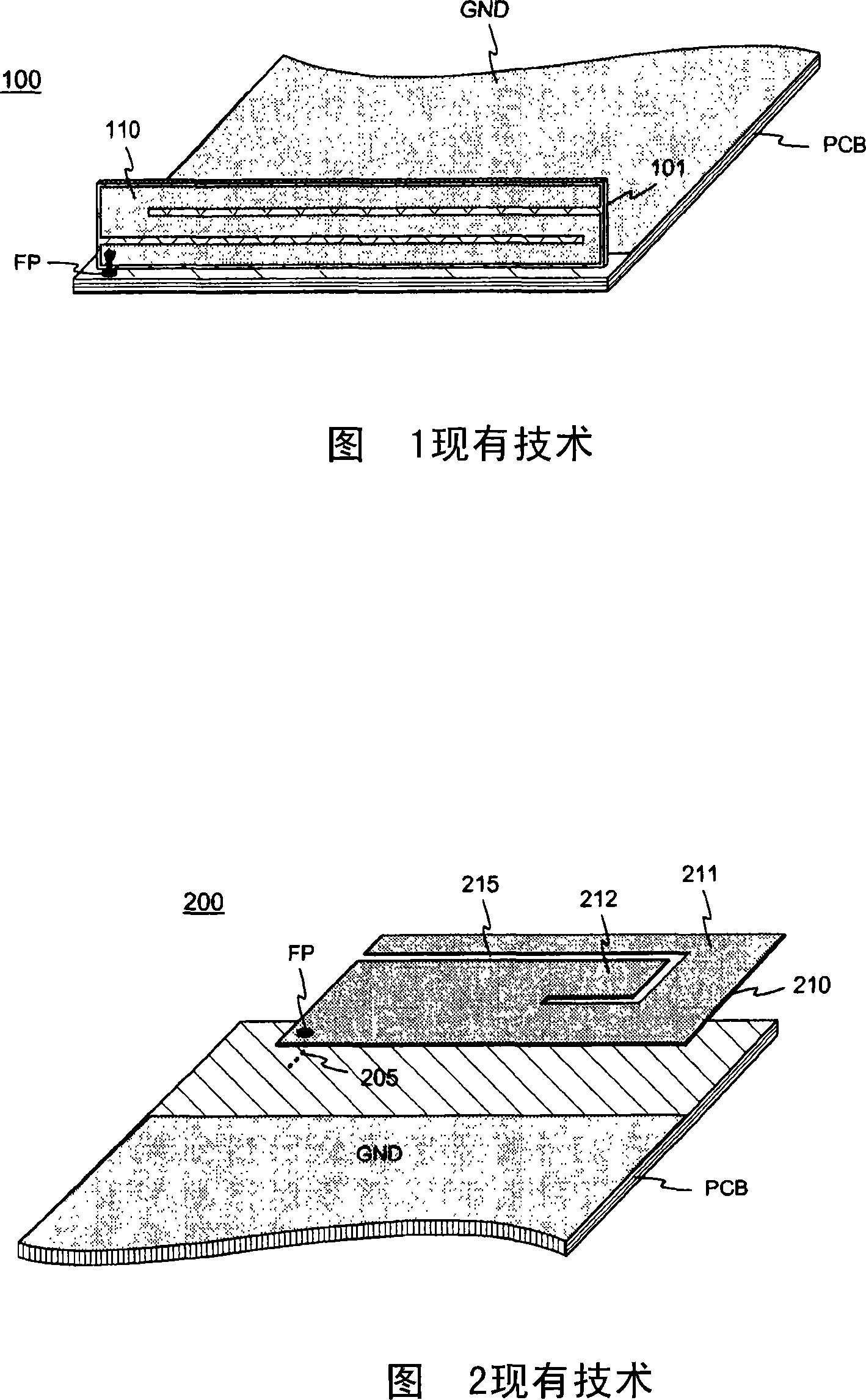
[0018] Figures 1 and 2 have already been explained in conjunction with the description of the prior art.

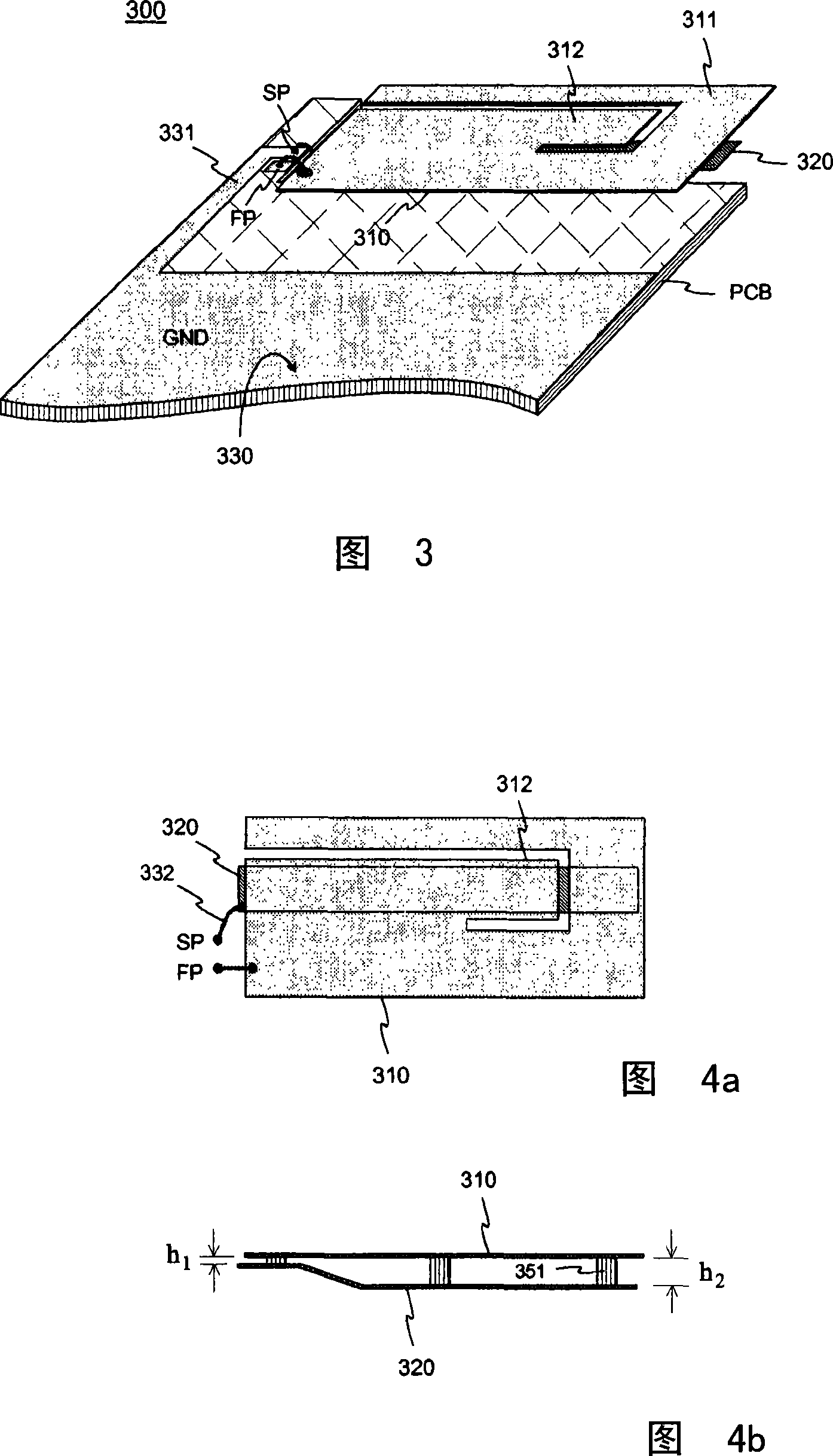
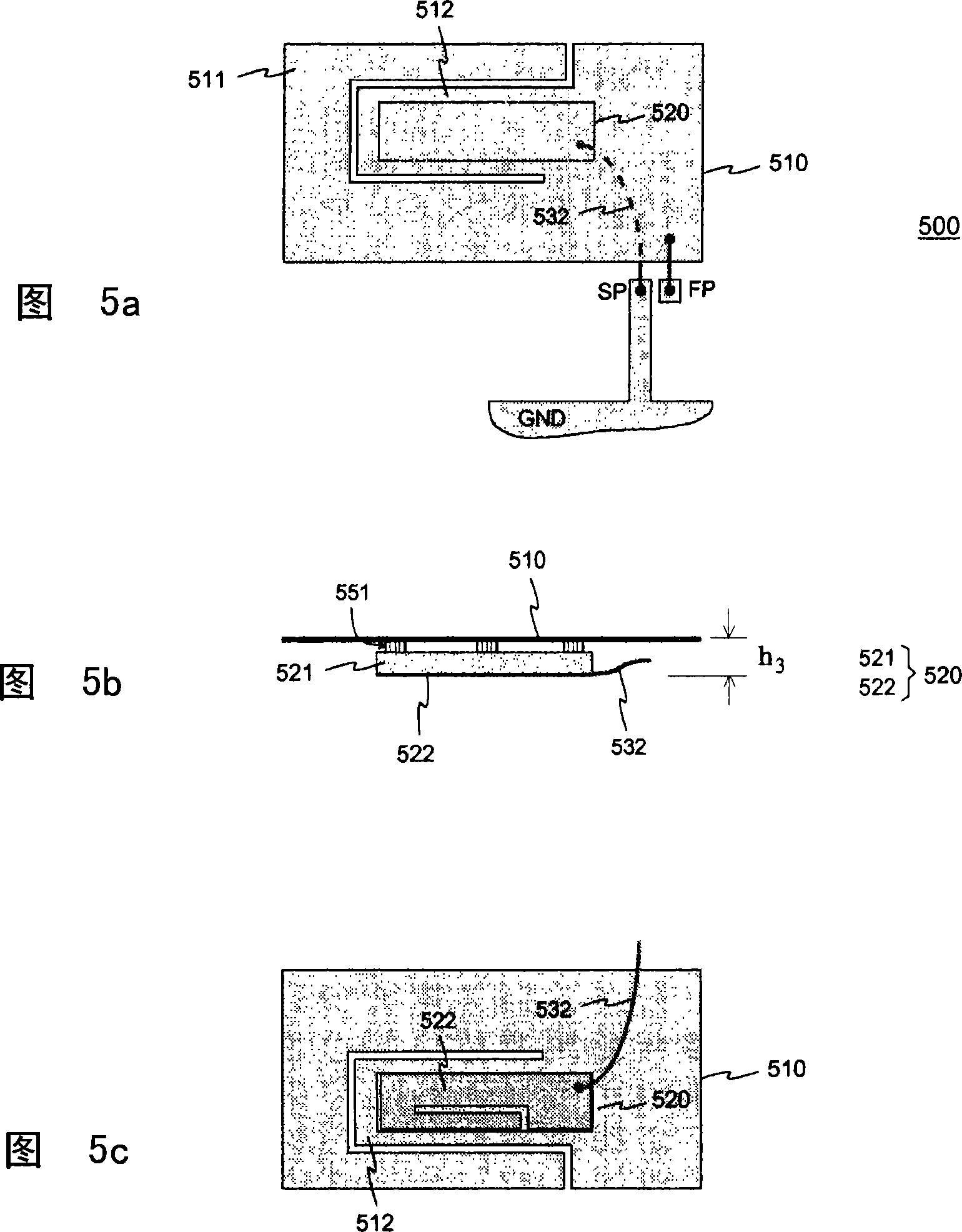
[0019] FIG. 3 shows an example of an internal monopole antenna of a radio device according to the invention. The main radiator 310 of the antenna 300 is a planar element at one end of the circuit board PCB of the radio device similar to the radiator 210 in FIG. 2 . In this example, the long side of the planar element slightly overlaps the circuit board. It can also be outside the circuit board when viewed from above. When viewed from its feed point FP, the planar element 310 has two branches of different lengths for forming two separate working strips. The longer branch 311 extends along the edge of the planar element around one end of the shorter branch 312 . On the circuit board PCB, there are some conductive coatings 330 which function as signal ground GND at a certain distance from the radiator 310 , or simply as ground. The antenna 300 also includes an auxiliary ...


PUM


Abstract

The invention relates to an internal monopole antenna of especially a flat a radio device, which monopole antenna has an arrangement for improving its characteristics. The antenna comprises a planar monopole radiator (310) and an auxiliary element (320), which is located at the point of the planar element as viewed in the direction of its normal. The auxiliary element can be a mere conductor strip or a ceramic plate partly coated with a conductor. The conductor of the auxiliary element is connected to the ground at a point (SP), which is relatively close to the feed point (FP) of the planar element. The planar element (310) can be shaped to form two operating bands for the antenna. The auxiliary element can be used to increase the bandwidth of the internal monopole antenna and / or to improve the omnidirectional radiation of the antenna.

Description

technical field [0001] The invention relates to an internal monopole antenna of a radio device having an arrangement for improving its characteristics. The antenna is especially intended for small and flat radios with multiple operating bands. Background technique [0002] The internal antennas of small-sized portable radio devices, such as mobile telephones, mostly often have a planar structure, which includes a radiation plane and a ground plane. To achieve sufficient electrical characteristics, the minimum distance between these planes must be close to one centimeter or more. This causes difficulties in the design of the antenna when the device is relatively flat, such as parts of a two-part communication device, where the parts are on top of each other, or consecutive one after the other, depending on the use case. For this reason, antennas of the monopole type, which do not require as much space as the above-mentioned flat antennas, are commonly used for such communic...

Claims


Application Information

Patent Timeline
Patent Type & Authority Applications(China)
IPC IPC(8): H01Q1/24H01Q9/04H01Q1/38H01Q5/02H01QH01Q5/00H01Q5/15H01Q5/371H01Q5/378
CPCH01Q1/243H01Q9/42H01Q5/0062H01Q9/40H01Q5/0058H01Q5/371H01Q5/378
Inventor A·拉帕纳M·库帕里A·伊索哈塔拉P·安纳马J·米科拉P·克斯基塔洛S·基洛南
Owner PULSE FINLAND
Learn More