Bicycle labor saving driving wheel

A technology for bicycles and driving wheels, which is applied in the directions of rider driving, vehicle components, transportation and packaging, etc., which can solve problems such as unreachable, and achieve the effect of being easy to accept and compact in structure

Inactive Publication Date: 2008-01-30
王继民
View PDF2 Cites 0 Cited by
  • Summary
  • Abstract
  • Description
  • Claims
  • Application Information

AI Technical Summary

Problems solved by technology

[0004] The purpose of the present invention is to provide a labor-saving drive wheel for bicycles, aiming to achieve the real labor-saving effect in view of the shortcomings of the prior art that cannot achieve real labor-saving

Method used


Image

  • Bicycle labor saving driving wheel
  • Bicycle labor saving driving wheel
  • Bicycle labor saving driving wheel

Examples


Embodiment Construction

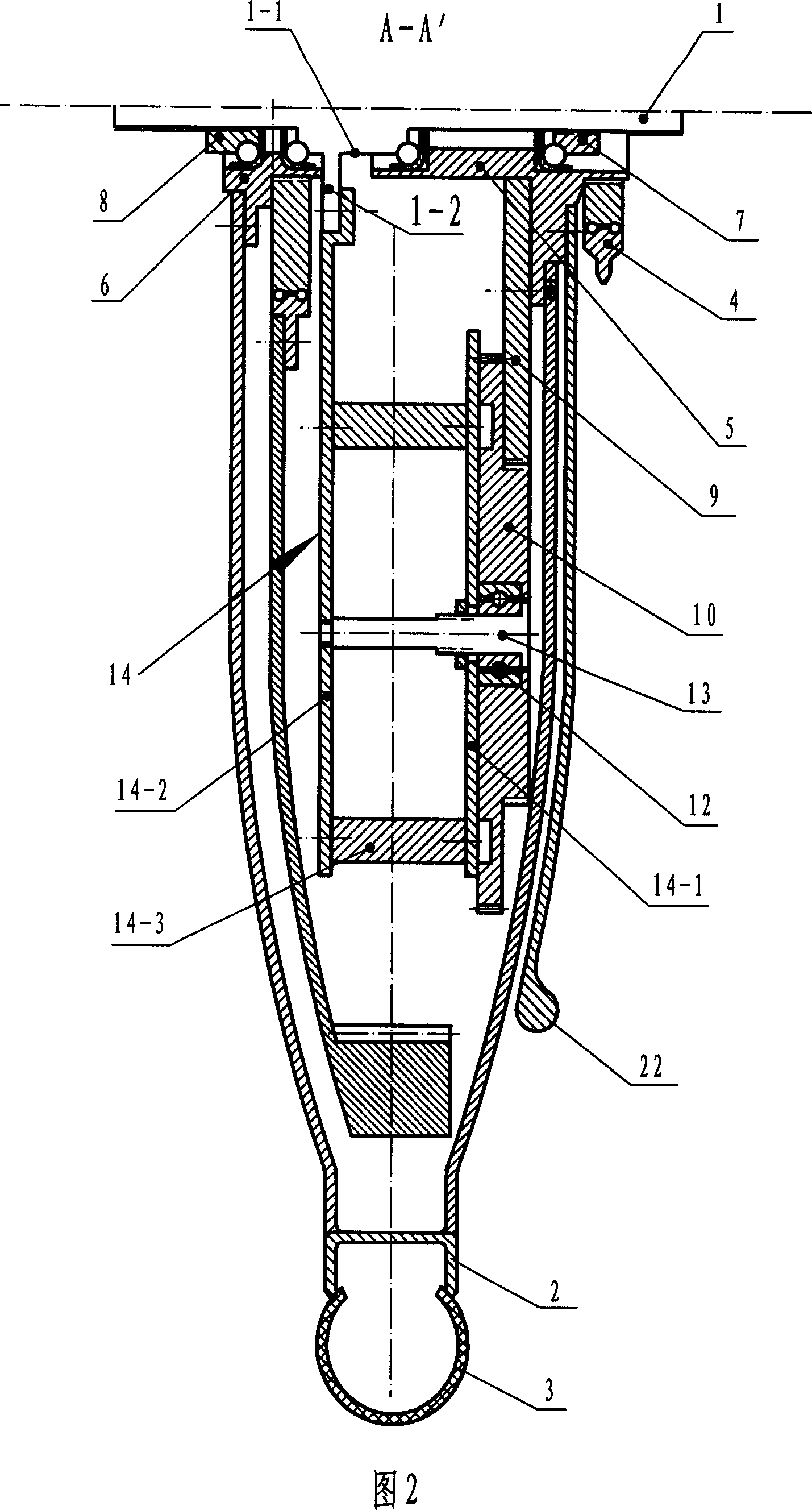
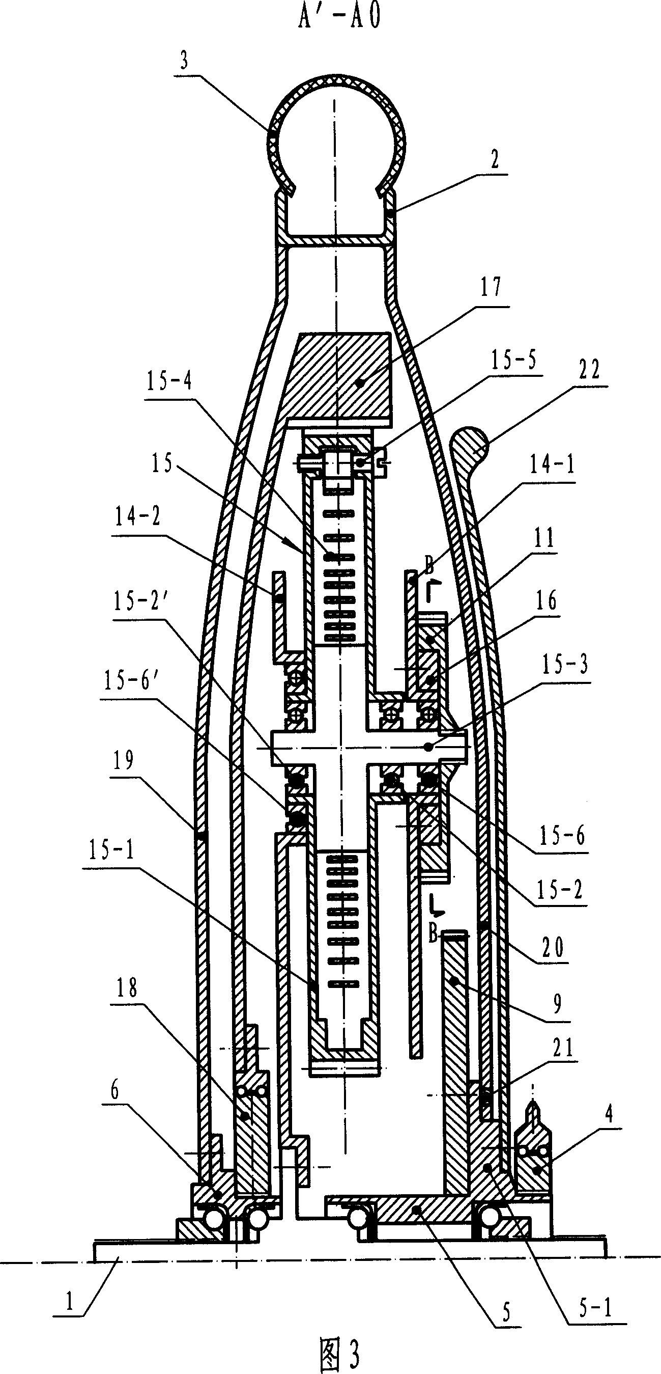
[0015] Referring to Fig. 1, 2, it comprises a bicycle rear wheel supporting shaft 1, rim 2, the tire 3 that is contained on the rim and a one-way overrunning clutch 4 (commonly known as rear flywheel) that links to each other with the faceplate on the center shaft by chain. ), the rear wheel support shaft 1 is covered with two left and right bead sleeves 5, 6, wherein the right bead sleeve 5 is used as the drive input shaft, and the left bead sleeve 6 is used as the drive output shaft, both of which can be wound around the rear wheel The support shaft 1 rotates, and the two ball sleeves are axially fixed by two nuts 7, 8 and the diameter-expanding section 1-1 located at the middle of the rear wheel support shaft 1; Connect the described one-way overrunning clutch 4, a driving gear 9 is fixedly connected at its left end, and the driving gear 9 is a half gear, and four evenly distributed intermediate gears 10 and four evenly distributed secondary gears are arranged around the dri...


PUM


Abstract

The invention relates to a bicycle effort-saving drive wheel, which includes an input ball sleeve and an output ball sleeve which are arranged on a rear wheel supporting shaft, a drive gear arranged on the input ball sleeve, and a plurality of middle gears and a plurality of driven gears arranged on the circumference of the drive gear; wherein, the drive gear drives the driven gear to rotate by the middle gear; the driven gear is arranged on a clockwork-spring wheel to drive the clockwork-spring to be tightened; a plurality of clockwork-spring wheels are engaged with an internal gear ring and release the spring force together driving the rotation of the internal gear ring; the internal gear ring drives the output ball sleeve to rotate and the rear wheel to rotate. The drive gear of the invention is the half gear which tightens a plurality of clock-work-spring wheels in groups by rotating in a circle, meanwhile, the invention can release in centralization the spring force of a plurality of the clockwork-springs by utilizing the structure of a plurality of clockwork-springs engaged with one internal gear ring, thus decomposing the input force by step and reaching the object of effort saving.

Description

Technical field [0001] The invention relates to an energy-storage bicycle, in particular to an energy-saving bicycle with spring energy storage. Background technique [0002] In the prior art, it is not uncommon to install a mainspring on a bicycle. Its purpose is to tighten the mainspring with the pedal force, and then use the mainspring release force to drive the vehicle forward, and finally achieve the purpose of saving energy by using the mainspring to assist. human purpose. But present friend this class structure is all not ideal enough, for example: Chinese patent 95204753.5, this patent connects a mainspring in series between the central shaft of the bicycle and the faceplate, when the pedal crank rotates, the crank drives the central shaft to rotate simultaneously, thus goes up Tighten the mainspring, when the tightening force of the mainspring is balanced with its release force (reaction force), the pedal force is transmitted to the face plate through the main spri...

Claims


Application Information

Patent Timeline
Patent Type & Authority Applications(China)
IPC IPC(8): B62M1/10
Inventor 王继民
Owner 王继民
Why Eureka
Try Eureka