Signal synchronization system

A signal synchronization and signal technology is applied in the field of how multiple receiving devices can correctly receive the data output by multiple output devices, which can solve the problems of rising cost of chip packaging circuit boards and complicated circuit layout of circuit boards, etc. Simple circuit layout and the effect of reducing the number of pins

Inactive Publication Date: 2008-01-16
BEYOND INNOVATION TECH
View PDF0 Cites 0 Cited by
  • Summary
  • Abstract
  • Description
  • Claims
  • Application Information

AI Technical Summary

Problems solved by technology

[0005] However, the traditional signal synchronization system 102 needs to set a set of chip pins for each receiving device. With the increase of output devices and receiving devices, the number of pins (pins) of the traditional signal synchronization system 102 will become a burden, not only the circuit board The circuit layout (circuit layout) will be quite complicated, and the cost of the package (package) of the chip (chip) and the cost of the circuit board (PCB) will also increase

Method used


Image

  • Signal synchronization system
  • Signal synchronization system
  • Signal synchronization system

Examples


Embodiment Construction

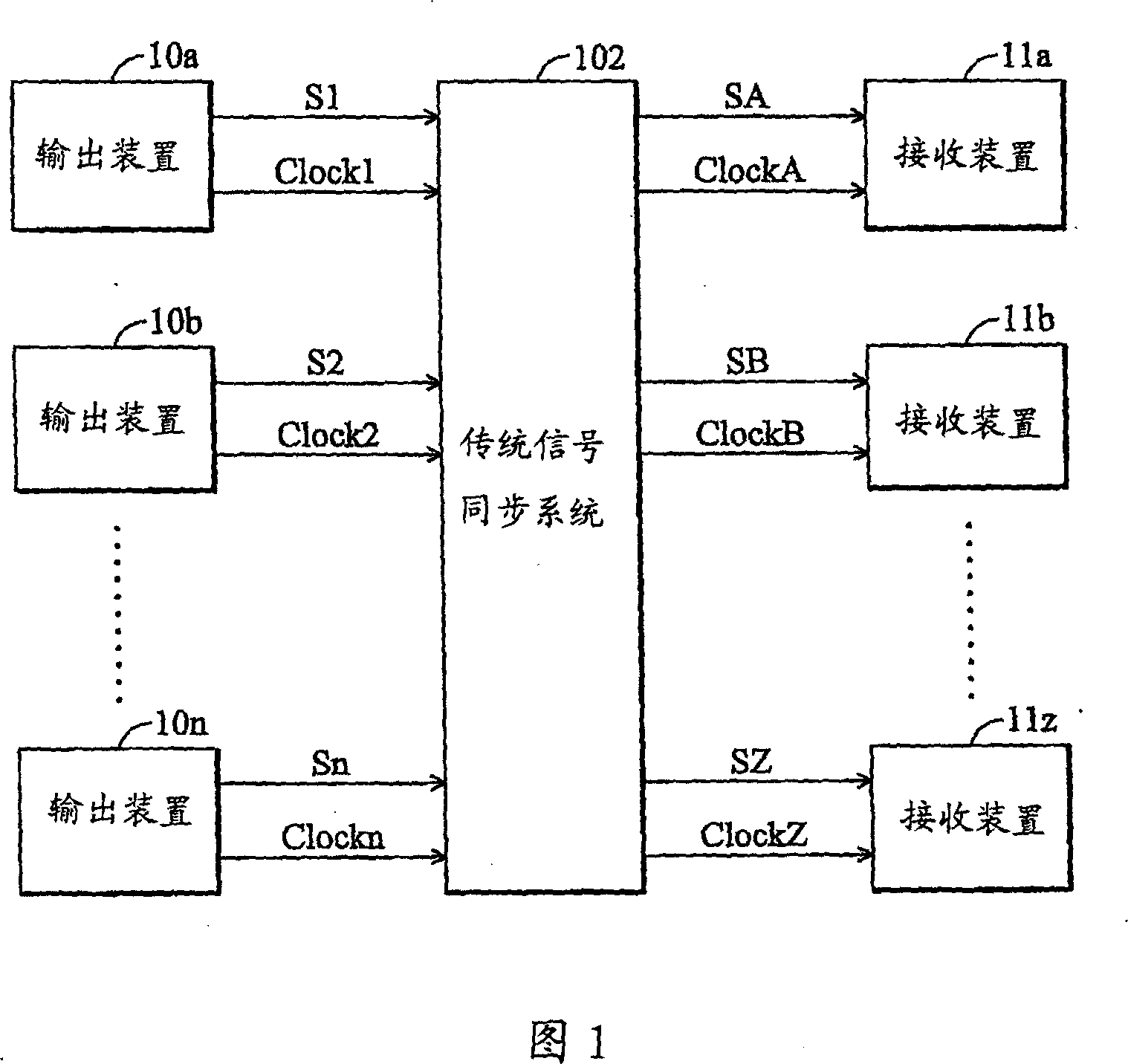
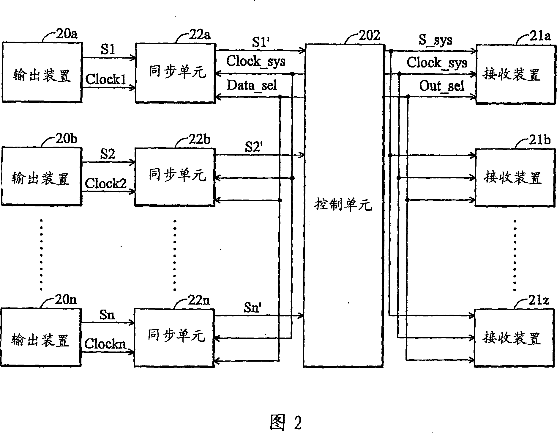
[0045] FIG. 2 is an implementation diagram of a signal synchronization system provided by the present invention. The signal synchronization system can be applied when multiple output devices transmit data to multiple receiving devices. The signal synchronization system includes a plurality of synchronization units 22a, . . . , 22n and a control unit 202 . The synchronization units 22a, . . . , 22n each correspond to an output device (respectively 20a, . . . , 20n). The control unit 202 generates a system clock Clock_sys and a data selection signal Data_sel according to the number n of the output devices and clocks Clock1 , . . . , Clockn. In the case of using the system clock Clock_sys, the order in which the control unit 202 receives data is determined by the data selection signal Data_sel. The content of the data selection signal Data_sel can be the codes of the output devices. For example, if the number of output devices is 2 (n=2) and the operating clock is 66MHz (Clock...


PUM


Abstract

A signal synchronization system comprises a plurality of synchronization units and a control unit. Each of the synchronization units corresponds to an output device respectively, allowing the control unit to correctively receive the output data from the output device. The control unit generates the system clock and the data selection signal according to the number of the output devices and the clock. The frequency of the system clock has to be high enough to allow the control unit to be able to receive all output data from the output devices. The data selection signal determines the order of data from the output devices received by the control unit. The control unit generates the output selection signal and arranges the output data from the output devices into the same signal to provide for a plurality of the receiving devices to receive. The output selection signal is used to label which receiving device should receive the data output by the control unit.

Description

technical field [0001] The present invention relates to a signal synchronization system, in particular to how multiple receiving devices correctly receive data output by multiple output devices. Background technique [0002] Signal synchronization has always been an important topic in electronic systems. For example, the transmission of multimedia information in the network system or the transmission of image information in the system requires signal synchronization technology so that the receiving device can correctly receive the data of the output device. [0003] The currently commonly used synchronization technology is: using a crystal oscillator to provide a reference frequency, and cooperating with a phase-locked loop (PLL) and a frequency divider to generate different working clocks for use by different devices in the system. However, the clock generated by the phase-locked loop usually has a noise problem, so that the working clocks of the various devices in the sys...

Claims


Application Information

Patent Timeline
Patent Type & Authority Applications(China)
IPC IPC(8): H04L7/08H04J3/06
Inventor 沈中理
Owner BEYOND INNOVATION TECH
Why Eureka
Try Eureka