
Tensioner for elevator overspeed preventer device

A technology of elevator speed limiter and tensioner, which is applied in the direction of transportation and packaging, elevators, etc.

Inactive Publication Date: 2010-09-29
TOSHIBA ELEVATOR KK
View PDF4 Cites 4 Cited by
  • Summary
  • Abstract
  • Description
  • Claims
  • Application Information

AI Technical Summary

Problems solved by technology

[0015]However, if the damping device that suppresses and damps the upward movement and vibration of the tensioner is simply attached to the guide mechanism, the overall planar projected area will be enlarged , making it difficult to install other equipment around the tensioner

Method used


Image

  • Tensioner for elevator overspeed preventer device
  • Tensioner for elevator overspeed preventer device
  • Tensioner for elevator overspeed preventer device

Examples


Embodiment Construction

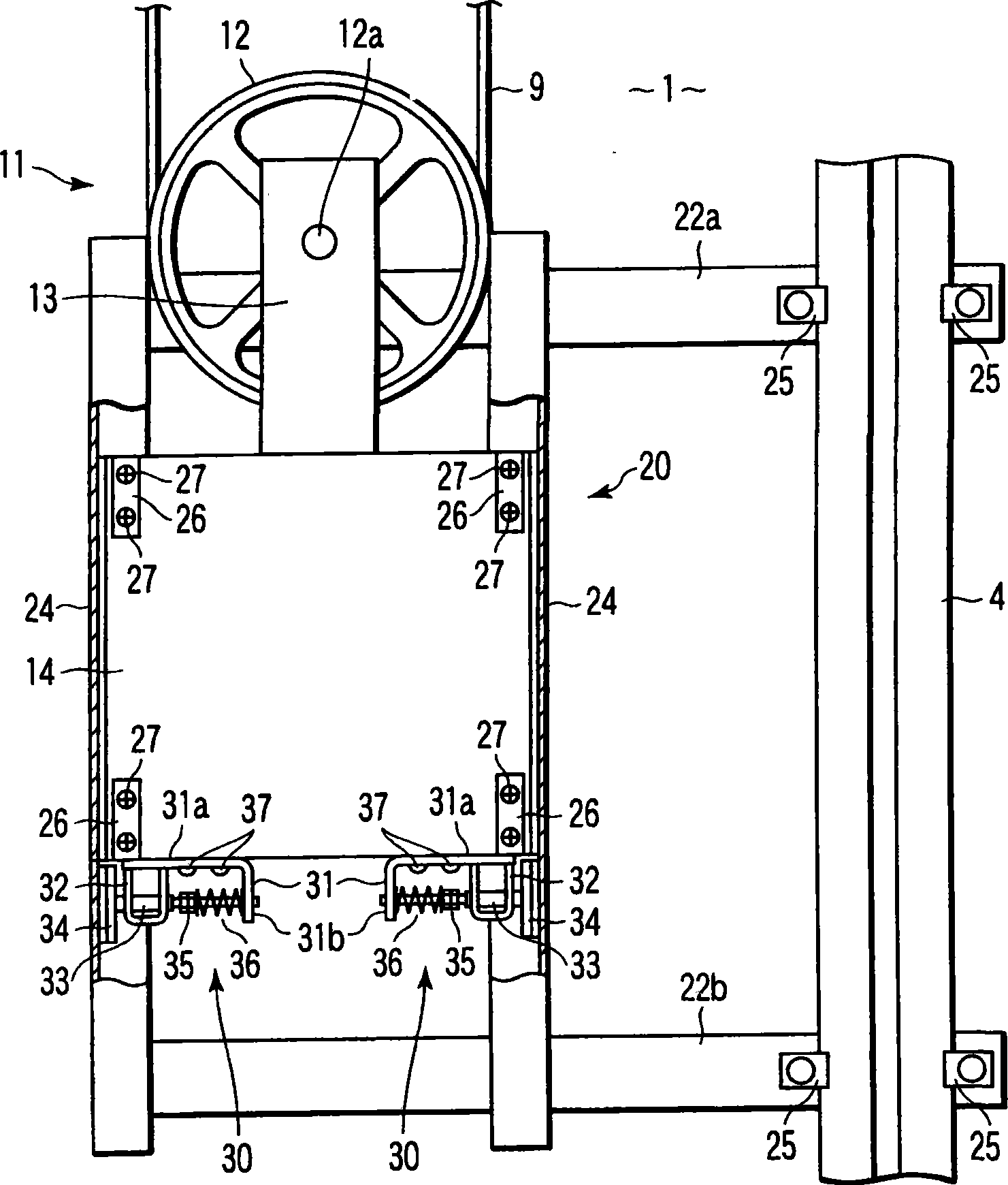
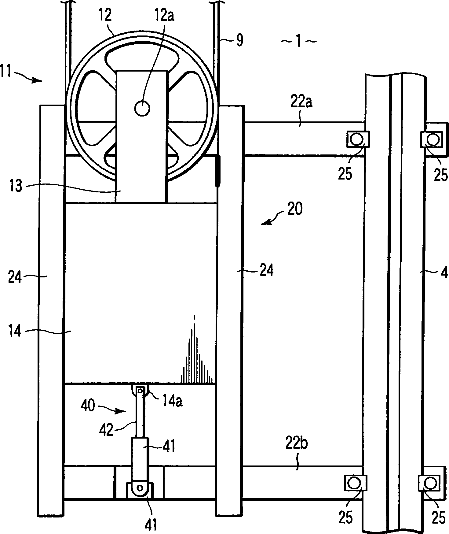
[0032] Hereinafter, embodiments of the present invention will be described with reference to the drawings. In addition, in each embodiment, for the Figure 11 The corresponding parts of the shown structures are marked with the same reference numerals and repeated descriptions are omitted.

[0033] exist figure 1 and figure 2 shows the first embodiment. The counterweight 14 of the tensioner 11 attached to the tensioner sheave 12 is guided by the guide mechanism 20 so that it can move up and down integrally with the tensioner sheave 12 .

[0034] The guide mechanism 20 has a pair of guide frames 24 supported by the guide rail 4 via brackets 22a and 22b. These guide frames 24 have a U-shaped cross section and are supported so that their open surfaces face each other and extend up and down. Further, both side edges of the counterweight 14 are slidably fitted inside the U-shape of the guide frame 24 . As a result, the counterweight 14 moves up and down along the guide frame ...


PUM


Abstract

A tensioner of an elevator speed governor apparatus is arranged with an attenuation devices (30, 40, 53, 62,68) which prevents and attenuates the oscillation generated when the speed governor rope (9) and balance weight (14) librate together up and down. The attenuation devices is configured in the projective area of the balance weight (14).

Description

Technical field [0001] The present invention involves the tensioner of the speed limit device of the elevator's speeding and the speed limit device of the car's emergency stopping device. Background technique [0002] Regarding the decline of elevator cars, for example, in the construction order of the Japanese construction benchmark, the following content is stipulated: one device must be set to automatically stop the decline in the car when the decrease of the car exceeds the specified value. [0003] Therefore, there is a limited -limited device on the elevator.Through this speed limiter device, the car is detected in a mechanical manner.In addition, when the decrease of the car exceeds the specified value, the emergency stop device operation assembled in the car.As a result, the car stops urgently. [0004] The rough structure of this speed limit device and the emergency stop device is expressed in Figure 11 middle.like Figure 11 It shows that in the lifting channel 1 of the ...

Claims


Application Information

Patent Timeline
Patent Type & Authority Patents(China)
IPC IPC(8): B66B7/06B66B5/04
Inventor 高井和彦
Owner TOSHIBA ELEVATOR KK
Learn More