Programmable sensing adjuster

A technology of regulators and programs, applied in the direction of instruments, regulating electrical variables, control/regulating systems, etc.

Active Publication Date: 2011-07-06
PHISON ELECTRONICS
View PDF6 Cites 0 Cited by
  • Summary
  • Abstract
  • Description
  • Claims
  • Application Information

AI Technical Summary

Problems solved by technology

[0005] 1. The reference voltage generation circuit A in the prior art can only choose to blow out the fuse B2 after the chip is manufactured, and cannot add a new fuse B2. Therefore, in order to It can achieve positive and negative two-way fine-tuning. Before the chip is processed, all fuses B2 are designed to be unburned (short circuit), so the output voltage A2 of its reference voltage generating circuit A must be low (such as Figure 2)
[0006] 2. The fuse B2 in the prior art uses current to blow out, and when the current is improperly controlled, it will destroy the circuit that generates the reference voltage A, so that the reference voltage generating circuit A loses its function
[0007]3. For the above-mentioned detection regulator, because the fuse must be blown to be able to distinguish logic "0" or "1", it needs to be installed on the chip before packaging. After completing the processing, if the logical "0" or "1" setting of the predicted demand cannot be clearly set, it is easy to cause the problem of material preparation

Method used


Image

  • Programmable sensing adjuster
  • Programmable sensing adjuster
  • Programmable sensing adjuster

Examples


Embodiment Construction

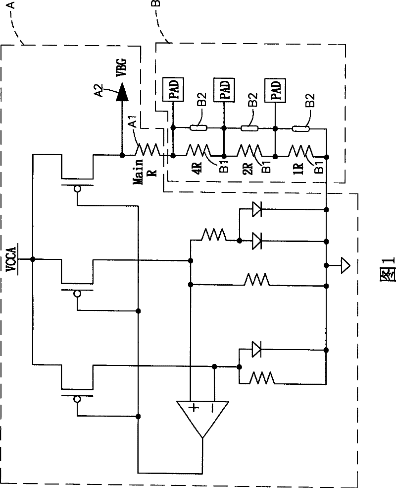
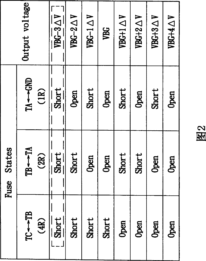
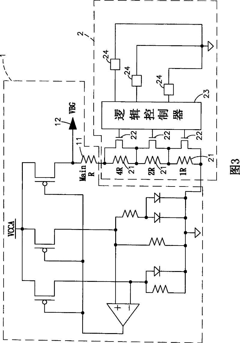
[0046] see image 3 Shown is the circuit diagram of the present invention. It can be clearly seen from the figure that the present invention connects the adjustment circuit 2 to the main resistor 11 provided in the voltage reference circuit (bandgap) 1, and the adjustment circuit 2 has complex and main resistors 11 The adjusting resistors 21 are connected in series, and the adjusting resistors 21 are respectively connected in parallel with transistor switches 22, and each transistor switch 22 is connected to a logic controller 23, and the logic controller 23 is sequentially connected with detection circuits 24 equal in number to the transistor switches 22.

[0047] Please also refer to image 3 , 4 Shown is the circuit diagram of the present invention and the schematic circuit diagram (1) of the programmable detection circuit. It can be clearly seen from the figure that when the output voltage (VBG) 12 output by the adjustment circuit 2 to the voltage reference circuit (bandg...


PUM


Abstract

A programmable detection regulator is prepared for serial-connecting master resistance of voltage reference circuit to regulation circuit, arranging multiple regulation resistance being series-connected with master resistance of voltage reference circuit on regulation circuit, parallel each resistance separately to relevant transistor switch being connected to logic controller, connecting logic controller in sequence to detection circuits in numbers equal to transistor switch to decide on-off state of relevant transistor switch for making micro-regulation on master resistance value of voltagereference circuit.

Description

technical field [0001] The present invention is a programmable detection regulator. No matter whether the internal detection circuit of the regulator is actually blown or not, the detection circuit will detect the resistance of the transistor switch and the resistance of the detection circuit. With the increased relative relationship, the logic controller can output "on" or "off" to the corresponding transistor switch according to the detection level signal it receives and cooperate with the logic conversion mechanism. Background technique [0002] At present, the semiconductor industry is moving towards a design-oriented trend, and under the leadership of this trend, the development of 3C integration and system-on-a-chip (SOC) is the hottest, because when the focus is on low price, high performance, and power saving Thin, light, small, and portable can only be achieved with more precise design technology and better manufacturing processes. Today, the number of transistors t...

Claims


Application Information

Patent Timeline
Patent Type & Authority Patents(China)
IPC IPC(8): G05F1/56
Inventor 林谕栋
Owner PHISON ELECTRONICS
Why Eureka
Try Eureka