
An injector

A technology of syringes and openings, applied in the field of syringes, can solve the problems of high consumption, damage, and hygiene problems of syringes, and achieve the effects of avoiding reuse, solving disposal, and superior cost competitiveness

Inactive Publication Date: 2007-12-26
宁湘龙
View PDF0 Cites 3 Cited by
  • Summary
  • Abstract
  • Description
  • Claims
  • Application Information

AI Technical Summary

Problems solved by technology

[0003] Since the syringe is a disposable sanitary product, after completing the above steps, the general practice is to separate the needle holder from the syringe and discard them separately, but because the needles are very sharp, it is difficult to properly store the discarded needles
In addition, due to the large consumption of syringes, although they are disposable consumables, they are sometimes reused because they cannot be properly disposed of after use, which has caused potential hygiene problems

Method used


Image

  • An injector
  • An injector
  • An injector

Examples


Embodiment Construction

[0025] The present invention provides a syringe that allows the needle to be pulled back into the barrel after use, thereby avoiding the thorny problem of needle handling. The specific real-time method of the present invention will be described in detail below with reference to the drawings.

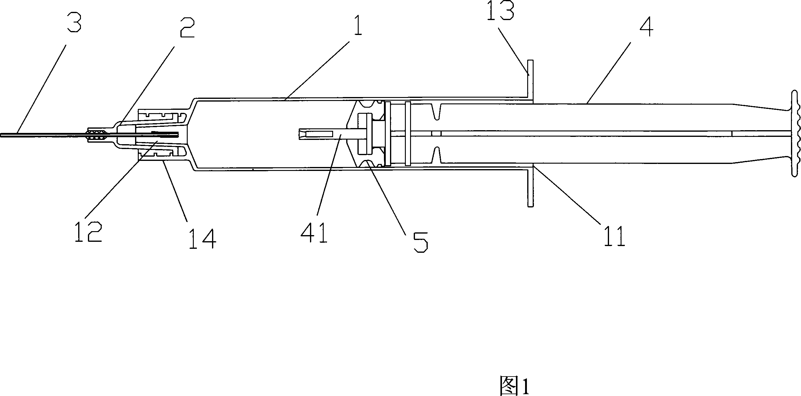
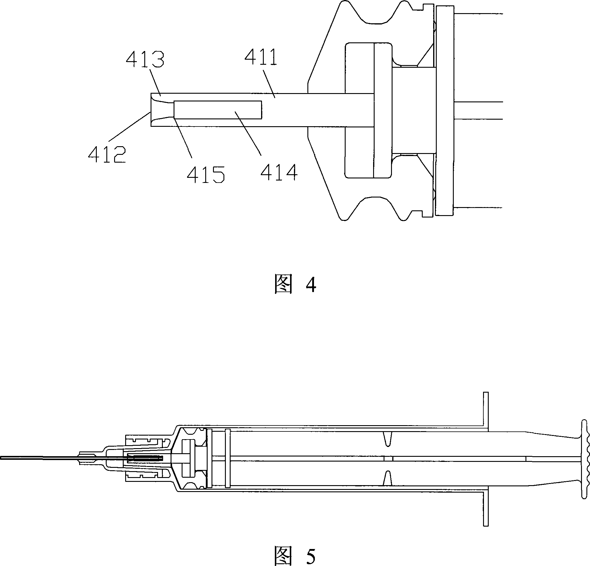
[0026] 1, the syringe according to the first specific real-time mode of the present invention includes a syringe 1, a needle holder 2, a hollow needle 3, and a push rod 4. The syringe 1 has a first opening 11 and a sharp mouth-shaped second Two openings 12, the first opening 11 can be provided with a radially outwardly extending plate 13 for placing fingers, and a needle holder connecting portion 14 can be provided outside the second opening 12. The structure of the needle holder connecting portion is existing It is well known in the art; the needle holder 2 is connected to the needle holder connecting portion 14 at the pointed mouth-shaped second opening 12 of the syringe 1, and includes a ...


PUM


Abstract

The present invention relates to an injector. It includes the following several portions: injector tube, injector needle seat, hollow injector needle and push rod. Said invention also provides the concrete structure of above-mentioned every portion, and also provides its concrete operation method.

Description

Technical field [0001] The invention belongs to a syringe, in particular to a syringe in which the needle can be pulled back into the barrel after the injection is completed. Background technique [0002] Syringe is a commonly used medical appliance, and its dosage is relatively large. The general structure of the syringe, as shown in Figure 1, includes a syringe. One end of the syringe has an opening with a larger radius and the other end has a pointed mouth; a needle holder is fixedly connected to the pointed mouth. The seat is fixedly connected with a needle, and also includes an opening with a larger radius from the needle barrel to fit a push rod in the needle barrel, and a rubber sealing plug is provided at the end of the push rod that enters the needle barrel. When in use, push the push rod to push out the air in the syringe from the needle through the sealing effect of the rubber stopper, and then pull the push rod in the opposite direction to suck the injection from the ...

Claims


Application Information

Patent Timeline
Patent Type & Authority Applications(China)
IPC IPC(8): A61M5/178A61M5/31A61M5/50
Inventor 宁湘龙
Owner 宁湘龙
Learn More