


Quick Research
Generate reliable direction feasibility study reports for your R&D in just a few steps.

Technical Q&A
Discover and master advanced knowledge NOW. Basics, ideas, possibilities, all at once.

Find Solutions
As an expert in R&D theories, this can generate solutions to your technical problems instantly.

Evaluate Feasibility
Analyze your overall solution with one click, know your potential R&D risks in advance.

Monitor Landscape
Get weekly tech updates, stay abreast of the latest tech innovations and key insights.
Core having insulating sheet and electric device provided with such core
A technology for electrical equipment and insulating sheets, which is applied to electrical components, circuits, magnetic cores/yokes, etc., can solve the problems of the number of assembly processes, the increase in component costs, and the inability to confirm whether to insert gap materials, so as to reduce the number of assembly processes, The effect of improving stability
- Summary
- Abstract
- Description
- Claims
- Application Information
AI Technical Summary
Problems solved by technology
Method used
Image

Examples
Embodiment approach 1
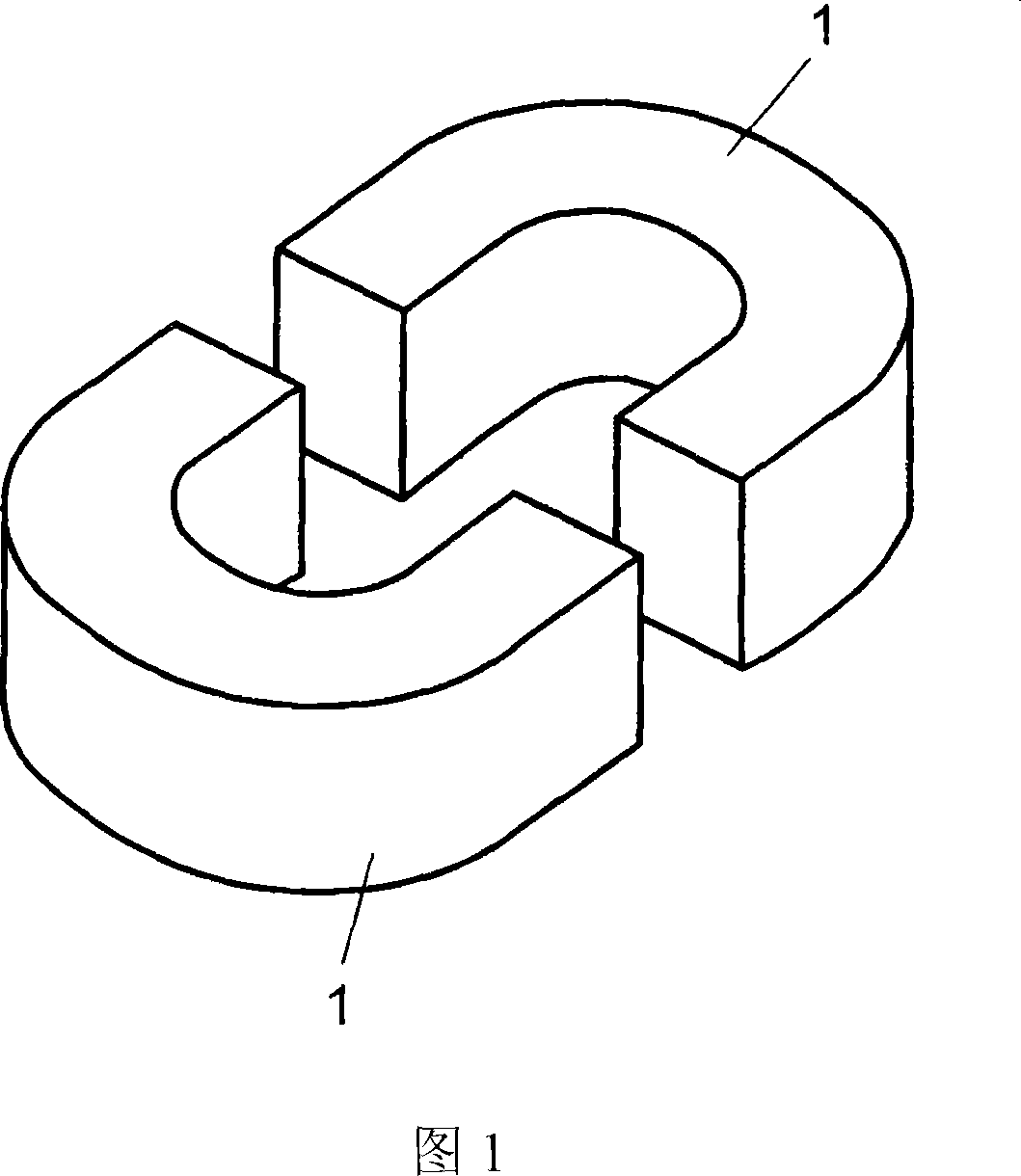
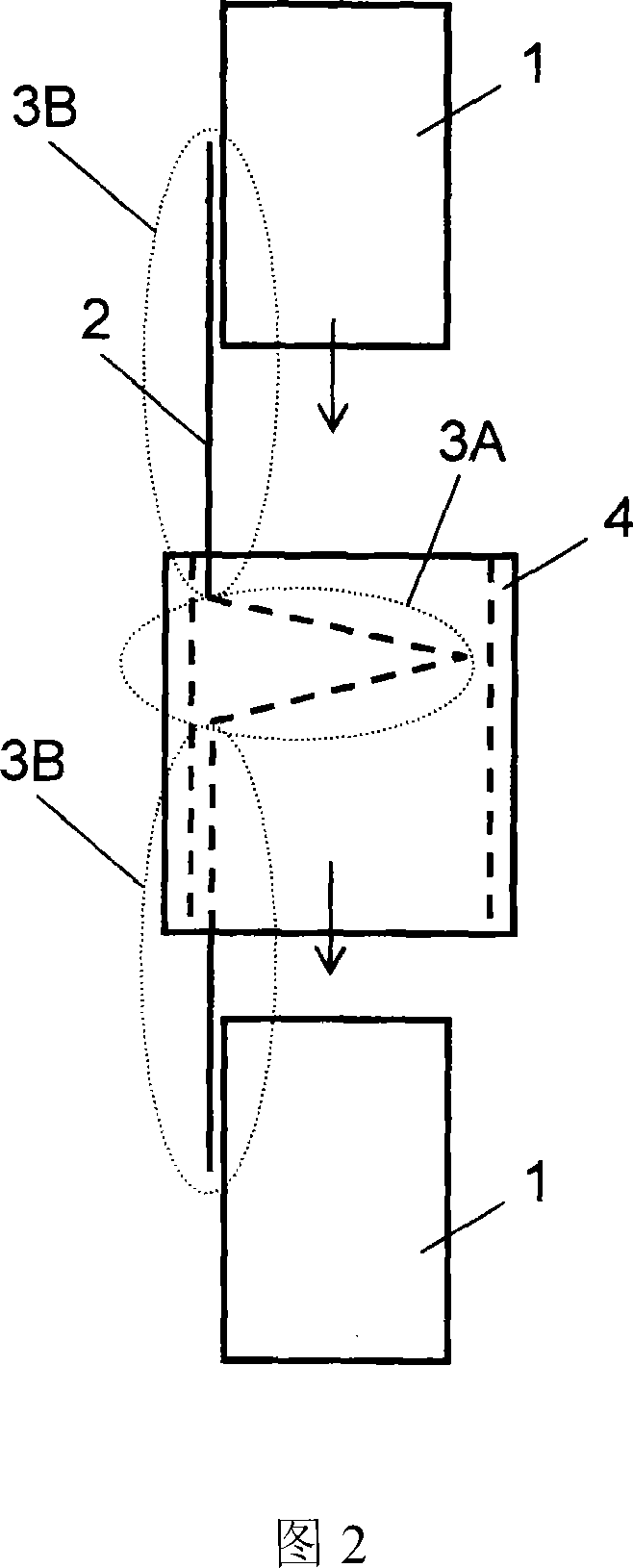
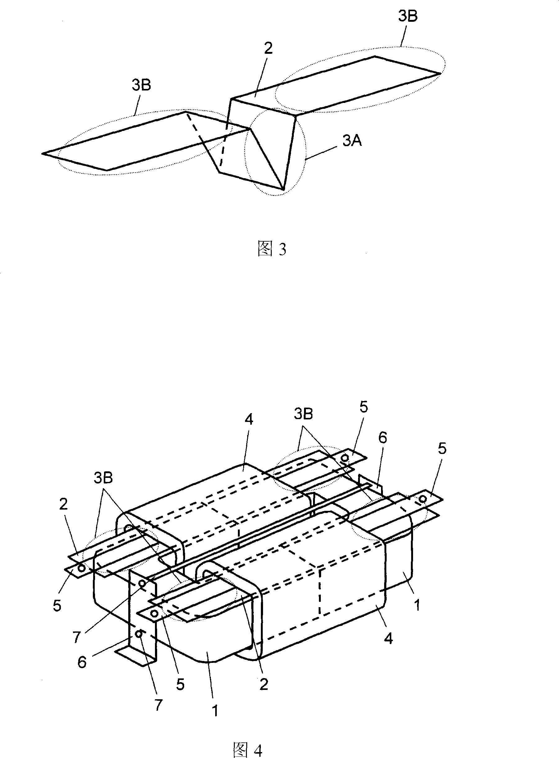
[0047] Embodiment 1 of the present invention will be described below with reference to FIGS. 1 to 4 . FIG. 1 is an external view of a set of U-shaped iron cores 1 constituting an iron core as an example of a core. FIG. 2 is an explanatory diagram for explaining the formation of the gap of the iron core. The iron core includes: a U-shaped iron core 1, a strip-shaped piece 2 described below, a V-shaped bending portion 3A of the strip-shaped piece 2, and a belt. The unbent portion of the sheet 2 (the portion other than the V-shaped bent portion 3A, hereinafter referred to as the unbent portion 3B), and the bobbin 4 . FIG. 3 is an external view of the strip sheet 2 . FIG. 4 is an external view showing a state in which the band piece 2, the U-shaped core 1, and the bobbin 4 are assembled.
[0048] Formation of the core gap in Embodiment 1 will be described below. As shown in FIG. 1 and FIG. 2 , for example, a pair of U-shaped cores 1 are configured to face each other. Furthermo...
Embodiment approach 2
[0062] In Embodiment 2, the same components as those in Embodiment 1 are assigned the same reference numerals, and detailed description thereof will be omitted.
[0063] The difference from Embodiment 1 is that, as shown in FIG. 5 , a continuous V-shaped bending portion 8A is produced by bending a part of the belt-shaped sheet 2 made of insulating material, and the continuous V-shaped The bent portion 8A is used to form a gap between the U-shaped cores 1 . Thus, by using the belt-shaped sheet 2 in which the continuous V-shaped bent portion 8A is produced, the thickness of the spacer can be doubled compared with the belt-shaped sheet 2 of FIG. 3 . In addition, if the V-shaped bending part is further added, the thickness of the spacer can be easily changed.
[0064] Next, the transformer according to Embodiment 2 will be described.
[0065] Although the shape of the bent part of the band-shaped piece 2 is different, as shown in FIG. The bent portion 8A can be clamped by the U...
Embodiment approach 3
[0071] In this third embodiment, the same components as those in the first embodiment are given the same reference numerals, and detailed description thereof will be omitted.
[0072] The difference from Embodiment 1 is that, as shown in FIG. 6 , an L-shaped bent portion 17A is formed by bending a part of a strip sheet 16 made of an insulating material, and is formed in an L-shape. Shaped ribbon sheet 16. This L-shaped bent portion 17A is used to form a gap between the U-shaped iron cores 1 . Thus, by using the strip-shaped sheet 16 in which the L-shaped bent portion 17A is formed, the length of the strip-shaped sheet 2 can be half that of the strip-shaped sheet 2 shown in FIG. 3 .
[0073] Next, the transformer according to Embodiment 3 will be described.
[0074] As shown in Figure 7, when assembling the U-shaped iron core 1, the bobbin 4, and the strip-shaped piece 16, the L-shaped bending portion 17A of the strip-shaped piece 16 is clamped by the U-shaped iron core 1, an...
PUM
 Abstract
Description
Claims
Application Information
 - R&D Engineer
- R&D Manager
- IP Professional
- Industry Leading Data Capabilities
- Powerful AI technology
- Patent DNA Extraction
Browse by: Latest US Patents, China's latest patents, Technical Efficacy Thesaurus, Application Domain, Technology Topic, Popular Technical Reports.
© 2024 PatSnap. All rights reserved.Legal|Privacy policy|Modern Slavery Act Transparency Statement|Sitemap|About US| Contact US: help@patsnap.com