Fuel injection pump having cavitation damage-prevention structure
A technology of a fuel injection pump and a protective structure, which is applied in the field of combustion of gas turbines, can solve problems such as failure to clarify the cause of damage, failure to reliably estimate and evaluate, etc.
- Summary
- Abstract
- Description
- Claims
- Application Information
AI Technical Summary
Problems solved by technology
Method used
Image
Examples
no. 1 approach
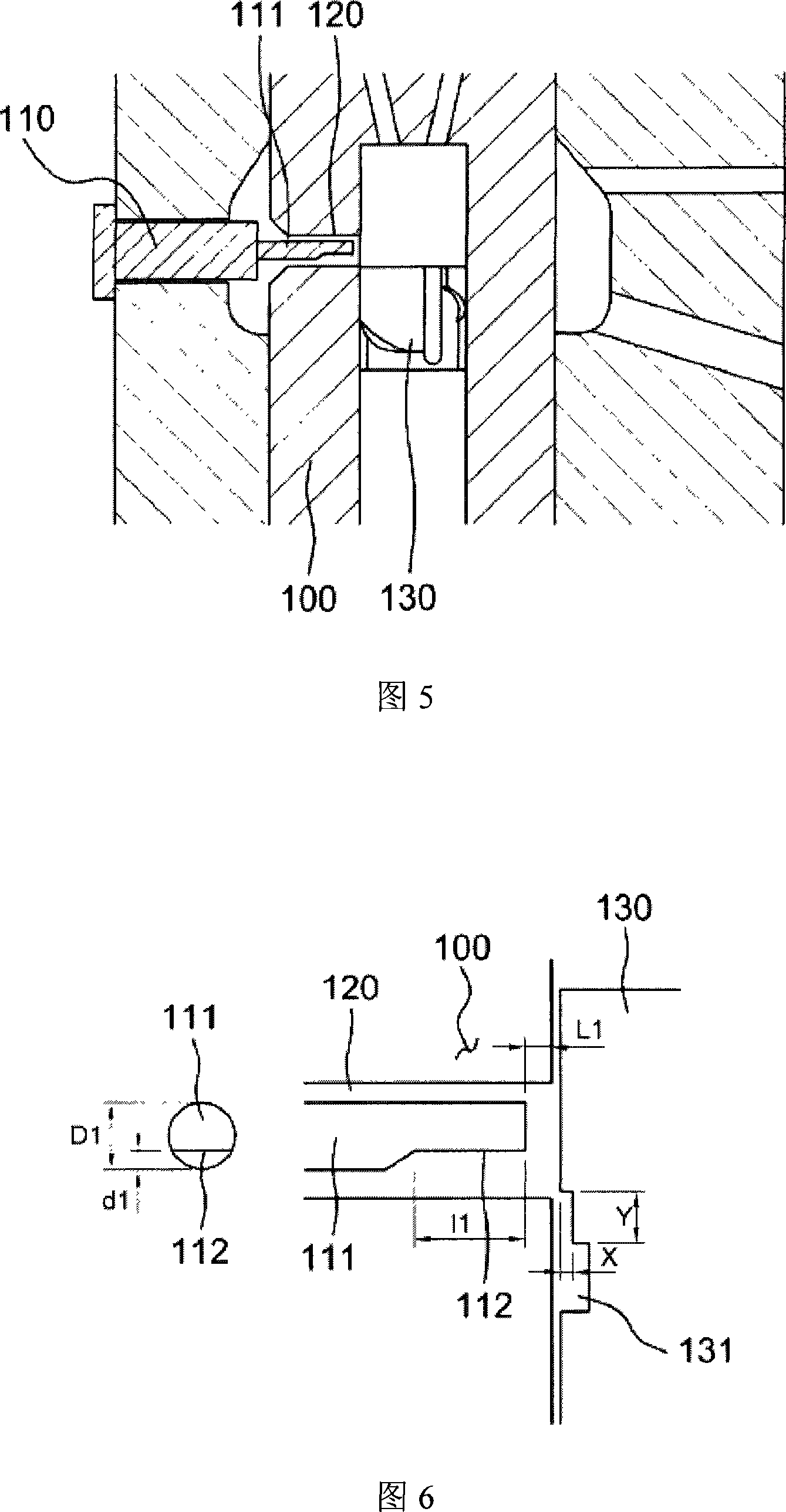
[0033] 5 is a cross-sectional view showing the structure of the fuel injection pump according to the first embodiment of the present invention. Referring to FIG. 5 , the fuel injection pump according to the first embodiment of the present invention is characterized by an improved structure of the deflector 110 for preventing the pump barrel 100 from being discharged to the pump at high speed and high pressure just after the effective stroke of the fuel injection pump. The oil return hole 120 is damaged due to residual fuel. The fuel injection pump having the above features can prevent the injection cavitation 20 that occurs just after the effective stroke of the fuel injection pump from directly impacting the oil return hole 120 . Also, the structure of the fuel injection pump makes it possible to prevent a pressure wave generated when cavitation strikes the oil return hole from propagating to the cavitation around the plunger 130 .
[0034] FIG. 6 is a view showing the struc...
no. 2 approach
[0040] 8 is a cross-sectional view showing the structure of a fuel injection pump according to a second embodiment of the present invention. 8, the fuel injection pump according to the second embodiment of the present invention is characterized by a modified shape of the oil return hole 210 defined in the pump barrel 200 for discharging residual fuel after the effective stroke of the fuel injection pump . The fuel injection pump having the above-described characteristics is due to the increased distance from the position at which the injection cavitation 20 occurs just after the effective stroke of the fuel injection pump to the position at which the injection cavitation impinges on the side of the oil return hole 210 . The structure makes the intensity of cavitation weaker and prevents pressure waves from propagating to the plunger 220 .
[0041] FIG. 9 shows the shape of the oil return hole 210 in detail. Referring to FIG. 9 , the shape of the oil return hole 210 is design...
no. 3 approach
[0047] 11 is a cross-sectional view showing the structure of a fuel injection pump according to a third embodiment of the present invention. 11 , the fuel injection pump according to the third embodiment of the present invention is characterized by an improved structure of the deflector 310 and the oil return hole 320 . The structure of the fuel injection pump having the above-mentioned features is such that the injection cavitation 20 that occurs just after the effective stroke of the fuel injection pump passes through the space defined between the deflector 310 and the side surface of the oil return hole 320, and even if it is caused by the injection The cavitation phenomenon 20 impacts the deflector to generate pressure waves, which can also prevent the pressure waves from propagating to the plunger 330 .
[0048] FIG. 12 shows the structure of the deflector 310 and the oil return hole 320 in detail. Referring to FIG. 12 , the deflector 310 includes a first tapered portion...
PUM
 Abstract
Description
Claims
Application Information
 - R&D Engineer
- R&D Manager
- IP Professional
- Industry Leading Data Capabilities
- Powerful AI technology
- Patent DNA Extraction
Browse by: Latest US Patents, China's latest patents, Technical Efficacy Thesaurus, Application Domain, Technology Topic, Popular Technical Reports.
© 2024 PatSnap. All rights reserved.Legal|Privacy policy|Modern Slavery Act Transparency Statement|Sitemap|About US| Contact US: help@patsnap.com


