Electric brake and energy recovery system for brushless DC motor

A technology of electronic braking and energy recovery, applied in the direction of stopping devices, etc., can solve the problems of interference control mechanism and low energy recovery ratio, and achieve the effect of reliable braking torque

Inactive Publication Date: 2007-12-12
WIZ ENERGY TECH
View PDF0 Cites 3 Cited by
  • Summary
  • Abstract
  • Description
  • Claims
  • Application Information

AI Technical Summary

Benefits of technology

This technology allows for easy control over reversely rotating electric motors by converting electrical signals into digital values that are easier to process with multiple phase wires compared to traditional methods like analog or pulse width modulation (PWM). It also provides smoother and more accurate regeneration of power from this recovered motion back onto itself without requiring complicated circuits.

Problems solved by technology

This patented technical solution describes various improvements made during the past decade towards improving the performance of conventional AC/MHG bicycle controllers. These advancements include reducing noise emissions, simplifying circuit construction, enabling faster response times without increasing load capacities, providing better regulation capabilities, ensuring stable stopability under different operating conditions, allowing for effective utilization of energy recovered devices, minimizing overall, the proposed solutions aimed to improve overall functionality and reliability of the electronic steering wheel drive system.

Method used


Image

  • Electric brake and energy recovery system for brushless DC motor
  • Electric brake and energy recovery system for brushless DC motor
  • Electric brake and energy recovery system for brushless DC motor

Examples


Embodiment Construction

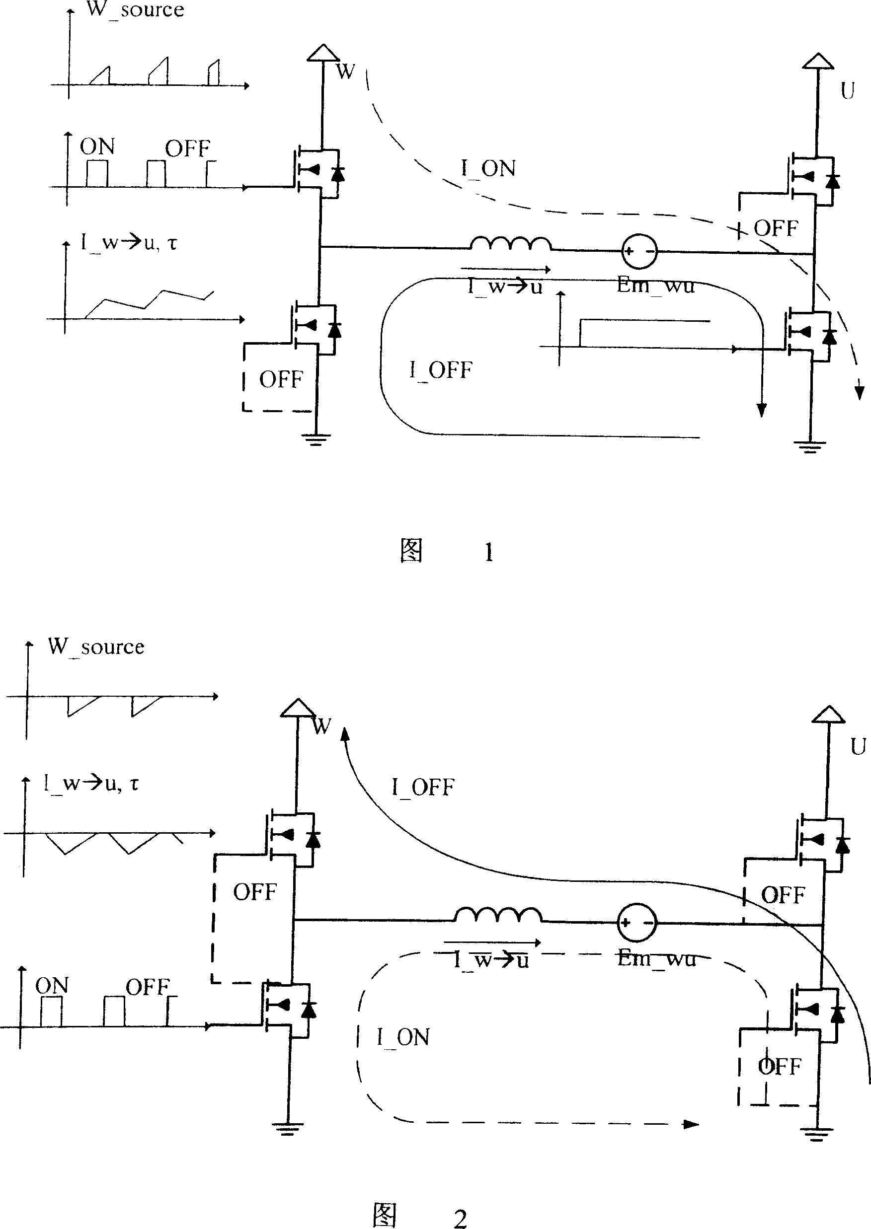
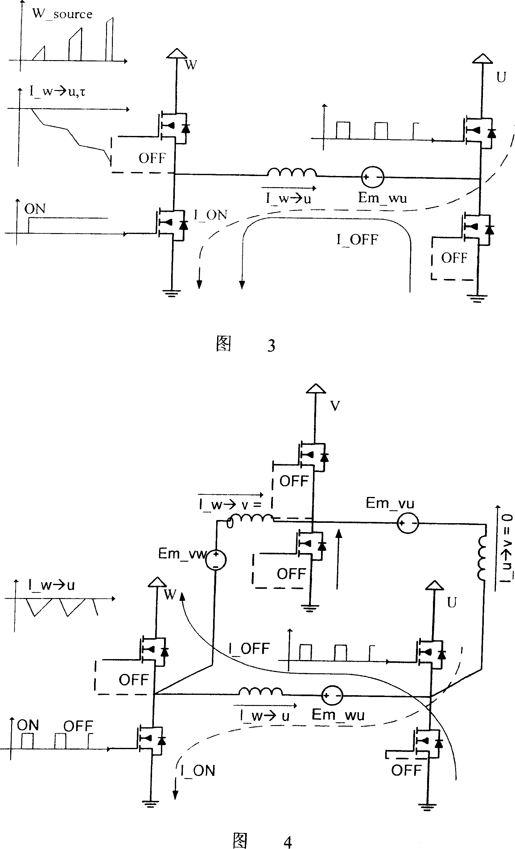
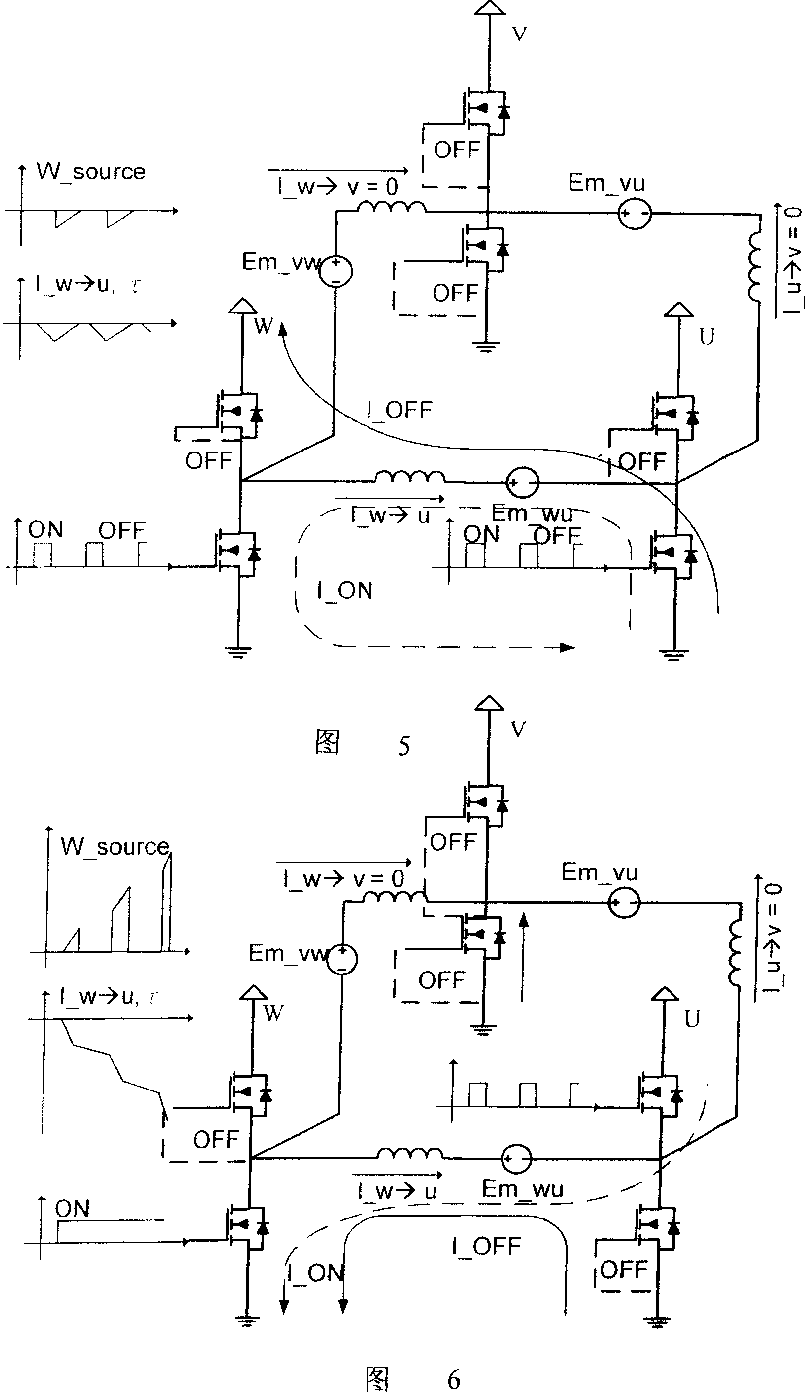
[0022] The electronic braking and energy recovery system used in the brushless DC motor of the present invention can be realized through simple electronic gate voltage signal conversion without changing the hardware structure of the original motor controller and motor. Practically control the function of the reverse torque brake, without the interference of multi-phase coils, and recover the kinetic energy of the motor to the maximum proportion. Please refer to Figure 7. The current direction of the motor coil under control is marked in the circuit. When the electronic brake system is activated, the controller applies the voltage on the motor coil in reverse mode. At this time, the current relationship on the motor coil is (volt Second Law, Voltage-Time Law: V_ motor ×Δt_ ON =L_ motor ×Δi_ motor )

[0023] (ε motor +V source )×Δt ON =L motor ×Δi motor (1), the only difference is that at this time the MOSFET on the left lower arm is not kept on (On Status), but is ...


PUM


Abstract

The energy recovery system applies reverse mode voltage on the motor coil when the electric brake system is activated, through synchronous switching controlling the up and down arm MOSFET, with the current flowing back to the source end when the arm closes, to achieve energy recovery. It relies on Gate voltage to switch signal, realizes the controllable reverse torque brake, provide smooth and reliable brake torque, without complex electric frame structure to recover the motor dynamic maximumly.

Description


Claims


Application Information

Patent Timeline
Owner WIZ ENERGY TECH
Why Eureka
Try Eureka