
Cutting edge for package container and package container having the same

A technology for packaging containers and cutting blades, applied in the field of cutting blades, can solve the problems of feeling (insufficient sense, problem of cutting performance, problem of durability feeling, etc.), achieve the effect of reducing load, reducing necessity, and improving durability

Active Publication Date: 2007-12-05
KUREHA KAGAKU KOGYO KK +1
View PDF4 Cites 13 Cited by
  • Summary
  • Abstract
  • Description
  • Claims
  • Application Information

AI Technical Summary

Problems solved by technology

[0010] However, according to the research of the present inventors, the cutting edge of the above-mentioned Patent Document 1 has the tip of each tooth of the paper serrated blade sharpened, but the size of each tooth is completely the same, so there is a problem in cutting performance.
In addition, in the cutting blades of Patent Documents 2 and 3 mentioned above, relatively large large teeth are provided in the central region compared to the side regions, so there are problems in durability, feeling at the time of cutting, etc.
In addition, in the cutting blade of the above-mentioned Patent Document 4, transitional cutting teeth are provided between the small cutting teeth arranged at the central portion and the large cutting teeth arranged at both ends, but the feeling (feel) at the time of cutting is not yet sufficient. full

Method used


Image

  • Cutting edge for package container and package container having the same
  • Cutting edge for package container and package container having the same
  • Cutting edge for package container and package container having the same

Examples


no. 1 approach

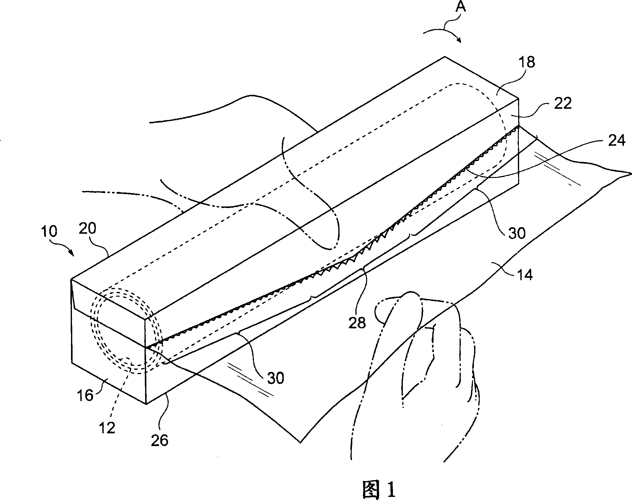
[0071] Fig. 1 is a perspective view showing the form of a packaging container 10 to which the present invention is applied. The packaging container 10 is made of a piece of thick paper, preferably clay coated newsback board. As shown in FIG. 1 , the packaging container 10 includes: a container main body 16 for accommodating a wrapping film 14 wound on a cylindrical paper tube 12 in a roll shape, and a cover body 18 integrally provided with the container main body 16 . When the lid is closed, the overall shape of the packaging container 10 is a substantially rectangular parallelepiped. In addition, in the present embodiment, the stretch film 14 is made of polyvinylidene chloride.

[0072] The upper portion of the container body 16 is opened as an opening for pulling out the wrap film 14 . Additionally, the lid 18 extends continuously from the top edge 20 of the rear wall of the container body 16 . Therefore, the lid body 18 can rotate relative to the container body 16 and c...

no. 2 approach

[0095] Fig. 3 is an enlarged view of a central portion of a cutting blade made of resin in a second embodiment of the present invention. The cutting blade 24 in the second embodiment has the same tooth structure in the central region 28 as the central region 28 of the cutting blade 24 in the first embodiment. However, the cutting blade 24 in the second embodiment is different from the cutting blade 24 in the first embodiment in that two types of side teeth having different sizes are provided in the side region 30 .

[0096] 4 is a partially enlarged view of one side region of a cutting blade made of resin in a second embodiment of the present invention. The cutting edge 24 of FIG. 4 includes: a plurality of side teeth (hereinafter referred to as "side first teeth") 31 having the same size as the small teeth 35 of the side region 30, and sandwiched by the first side teeth 31, Side teeth (hereinafter referred to as “side second teeth”) 32 smaller than the side first teeth 31 . ...

no. 3 approach

[0110]5 is a partially enlarged view of one side region of a cutting blade made of resin in a third embodiment of the present invention. Although not shown, the cutting blade 24 in FIG. 5 has the same tooth structure in the central region 28 as the central region 28 of the cutting blade 24 in the first and second embodiments. But the cutting edge 24 of Fig. 5 is equipped with in the side area 30: side teeth (hereinafter referred to as "side 3rd teeth") 33 smaller than the small teeth 35, and sandwiched by the side 3rd teeth 33, smaller than the side teeth 35. A plurality of side teeth (hereinafter referred to as "side fourth teeth") 34 having larger teeth 35 and smaller than the middle teeth 36 differ from the cutting blades 24 in the first and second embodiments. In the side area 30, the third side teeth 33 are arranged adjacent to the middle blade 36d belonging to the central area 28, and the third side teeth 33 and the fourth teeth 34 are located in the longitudinal directi...


PUM


Abstract

Provided are a non-metallic V-shaped cutting blade capable of cutting roll-shaped packaging materials such as wrapping films with very light force, and a packaging container provided with the cutting blade. The cutting edge (24) of the present invention includes a central region (28) and side regions (30) that are arranged on both sides of the central region and are composed of a plurality of side teeth (31). A middle tooth (36) and a plurality of large teeth (38). One of the large and medium teeth is arranged at the apex of the V-shape, and the other large teeth are arranged at predetermined intervals so as to sandwich the teeth at the apex. The middle teeth are arranged between the large teeth. The large gear is more prominent than the middle gear. With this structure, when the cutting starts, the large teeth pierce the wrapping film (14) first, and then the middle teeth pierce the wrapping film. Since the wrapping film is pierced through such two stages, the force required for cutting is small.

Description

technical field [0001] The present invention relates to a packaging container for packaging a wrap film (wrap film) wound around a cylindrical core in a roll shape, and particularly relates to a cutting blade used in the packaging container. Background technique [0002] Various types of packaging containers for stretch films are known. Most of them are made of thick paper, and include a container main body for accommodating a wrapping film wound into a roll, and a cover integrally provided with the container main body. Then, the wrapping film pulled out from the container is cut off with a serrated cutting edge installed on the inner surface of the front wall of the cover. [0003] As such a cutting blade, in order to easily cut the film, instead of a linear cutting blade, a V-shaped cutting blade in which the middle portion of the cutting blade is closer to the bottom of the container than the side regions has come to be used. This shape cuts the wrapping film from the m...

Claims


Application Information

Patent Timeline
IPC IPC(8): B65H35/06B26D1/02
Inventor 秀冈诚海野诚梅津正那须麻子关孝幸
Owner KUREHA KAGAKU KOGYO KK
Learn More