
Laser radar remote sensing polarized imaging system

A technology of laser radar and polarization imaging, which is applied in the radio wave measurement system, electromagnetic wave re-radiation, utilization of re-radiation, etc., can solve the problems that cannot be applied to the field of target recognition, and cannot obtain target polarization information.

Inactive Publication Date: 2007-11-28
BEIHANG UNIV
View PDF1 Cites 17 Cited by
  • Summary
  • Abstract
  • Description
  • Claims
  • Application Information

AI Technical Summary

Problems solved by technology

The institute's patent of "Micro-scattering polarization micro-pulse lidar control method and device", the patent number is CN1641339A, is mainly used for the research on the polarization characteristics of atmospheric environment, aerosol and other targets, but because the system does not have a polarization state generation system, it can only Emitting polarized laser light in a specific state cannot obtain complete polarization information of the target and cannot be used in the field of target recognition

Method used


Image

  • Laser radar remote sensing polarized imaging system
  • Laser radar remote sensing polarized imaging system
  • Laser radar remote sensing polarized imaging system

Examples


Embodiment Construction

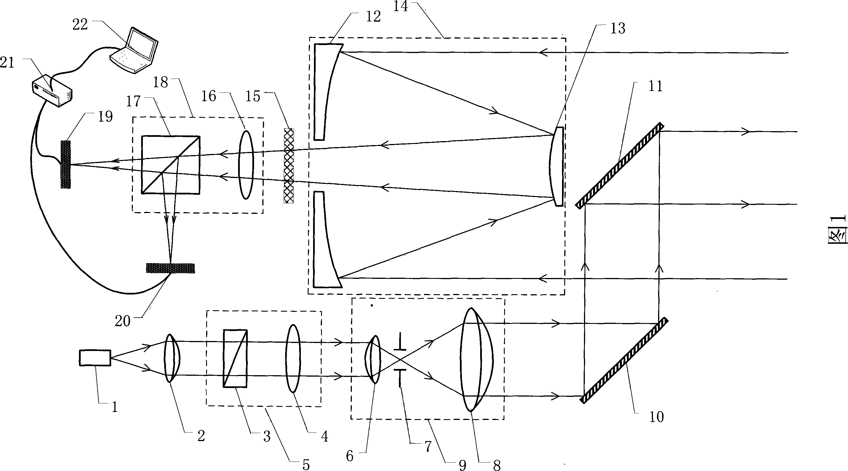
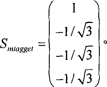
[0019] Figure 1 shows the remote sensing system diagram of the Lidar Polarization Radar. The polarization characteristics of the backscattered light of the target can characterize the essential characteristics and important parameter characteristics of the target; and it can effectively identify man-made targets in natural and complex backgrounds. As shown in Figure 1: The semiconductor laser (1) has a wavelength of 808nm, passes through a plano-convex collimator lens (2), and enters the polarization state generation system (5). The polarization state generation system (5) consists of Glan laser prisms (3) and 1 / 8 wave plate (4), in which the angle between the transmission axis of the Glan laser prism (3) and the x axis is -72.385°, and the angle between the fast axis of the 1 / 8 wave plate (4) and the x axis is 45° . The Stocks vector of the light after passing through the polarization state generating system (5) is: S mtagget = ...


PUM


Abstract

The invention provides a new radar remote-sensing polarization imaging system. It can make use of polarization information of target backward scattered light to carry out radar remote-sensing detection for target and quick real-time polarization degree imaging. The system comprises semiconductor laser, polarization-status generating system, beam expanding system, cassegrain telescope system, polarization-status detecting system, and data collecting and imaging system. The invention realizes polarization degree detection by the polarization-status generating system and the polarization-status detecting system and adopts polarization splitting prism in the polarization-status detecting system to realize a first detection for target polarization degree and real-time imaging.

Description

1. Technical Field [0001] The invention discloses a laser radar remote sensing polarization imaging system that uses polarization information to perform accurate remote sensing detection and imaging. It is mainly used in the detection, recognition and imaging of man-made targets in natural and complex backgrounds in military systems; remote sensing detection of comprehensive information on the types, growth, and health of vegetation and crops in civil systems. 2. Background technology [0002] Traditional lidar usually uses the flight time (distance parameter) of sending / receiving pulses, the echo intensity parameter, the backscatter waveform parameters of the target to the laser pulse, and the target space angle parameter (three-dimensional imaging system) obtained by the scanning angle. Considering the polarization characteristics of the target, it can't identify natural and man-made targets well; and it can't describe the essence and internal characteristics of the target well...

Claims


Application Information

Patent Timeline
IPC IPC(8): G01S7/481G01S17/02
Inventor 江月松赵一鸣张绪国
Owner BEIHANG UNIV
Learn More