Forced controlling hinge of hiding type device between side frame and wing fan

A hidden, framed technology, used in pinned hinges, wing parts, door/window accessories, etc., can solve the problem of not being able to fully guarantee the rotation sequence of hinge arches, and achieve the effect of increasing wear or seizure

Active Publication Date: 2011-04-13
DR HAHN
View PDF1 Cites 0 Cited by
  • Summary
  • Abstract
  • Description
  • Claims
  • Application Information

AI Technical Summary

Problems solved by technology

This type of hinge is particularly unsuitable for larger and thus heavier leaves, such as doors or windows, since the controlled pivoting sequence of the hinge legs about the hinge axis of the frame and the hinge axis of the leaf cannot be sufficiently guaranteed

Method used


Image

  • Forced controlling hinge of hiding type device between side frame and wing fan
  • Forced controlling hinge of hiding type device between side frame and wing fan
  • Forced controlling hinge of hiding type device between side frame and wing fan

Examples


Embodiment Construction

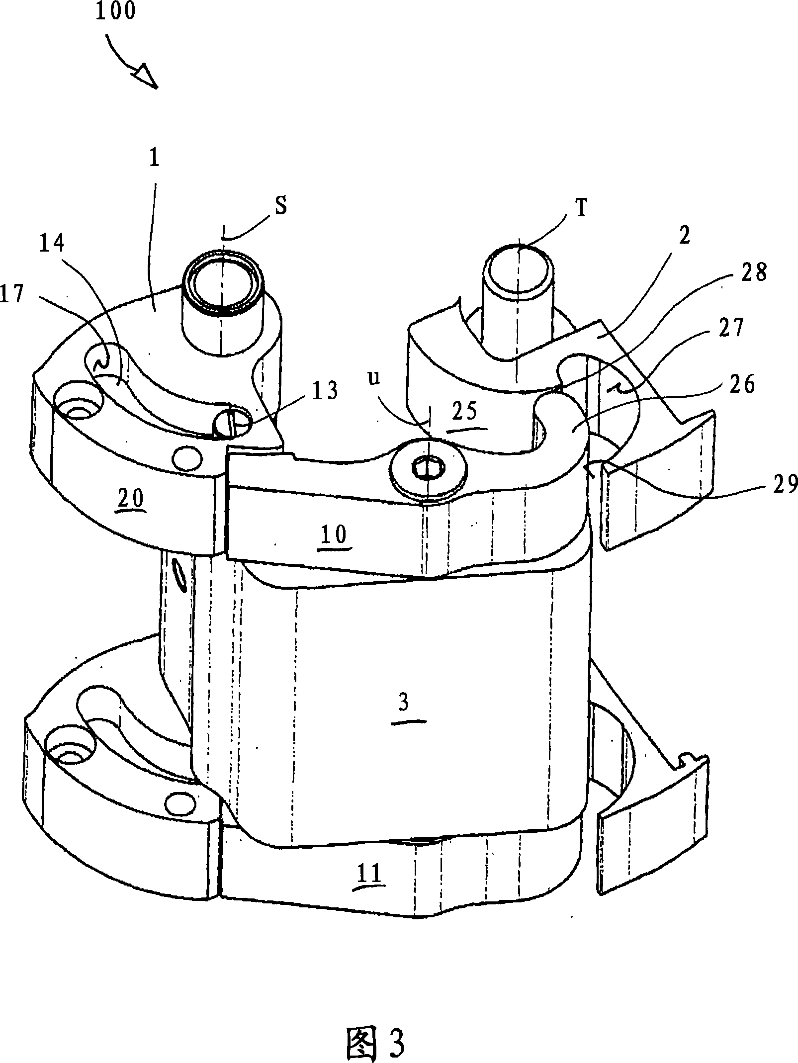
[0027] The hinge represented by 100 includes a frame hinge part 1 that can be installed on a frame not shown in the figure, especially in a mounting cavity provided in the frame for this purpose, and a frame hinge part 1 that can be mounted on a frame that is not shown in the figure. A leaf hinge part 2 on the leaf, in particular in a mounting cavity provided in the leaf. In addition, the hinge 100 also includes a substantially U-shaped hinge bow 3 .

[0028] The hinge link 3 is mounted at one end on the frame hinge part 1 so as to be pivotable about the frame hinge axis S by means of a frame pivot pin 4 . The other end of the hinge link 3 is likewise mounted rotatably about a leaf hinge axis T extending parallel to the frame hinge axis S on the leaf hinge part 2 by means of a leaf pivot pin 5 . The hinge bracket 3 has a lever 10 , 11 belonging to the locking pawl arrangement 8 , 9 on its end sides 6 , 7 , which are shown above and below in the figure, respectively, and the l...


PUM


Abstract

An instrument panel of a motorcycle is provided that includes a vehicle-use meter located on an upper portion of a fuel tank and covered by a meter cover. A manipulation switch, with communicates with the vehicle-use meter, is attached with a side surface of the meter cover.

Description

technical field [0001] The invention relates to a hinge, in particular for a concealed device between the frame and the leaf of a door or window. Background technique [0002] Such a hinge is known from GB2203483A. In order to ensure that the rotary movement of the hinge bow plate is carried out around the hinge axis of the wing leaf according to the control when the leaf opening angle reaches 90 degrees, and around the hinge axis of the frame when the opening angle is greater than 90 degrees, this hinge has a stop pawl device. The latter consists of a lever which is mounted on the hinge bracket so as to be pivotable about a hinge axis parallel to the hinge bracket. [0003] The frame hinge part and the leaf hinge part each comprise a cam device which cooperates with one of the two end regions of the lever. The lever is spring-loaded by a return spring acting between it and the hinge bracket, so that the end region of the lever on the leaf side is pressed against the cam s...

Claims


Application Information

Patent Timeline
Patent Type & Authority Patents(China)
IPC IPC(8): E05D3/06
CPCE05D3/127E05Y2900/531E05D3/12E05D11/1007E05Y2900/148E05Y2900/132
Inventor M·伦策
Owner DR HAHN
Why Eureka
Try Eureka