
Piezoelectric resonator and method for manufacturing thereof

A technology for piezoelectric vibrators and manufacturing methods, which is applied to electrical components, impedance networks, etc., can solve problems such as limiting the miniaturization of piezoelectric vibrators, and achieve the effect of increasing the number

Inactive Publication Date: 2007-11-07
TOYO TSUSHINKI
View PDF1 Cites 14 Cited by
  • Summary
  • Abstract
  • Description
  • Claims
  • Application Information

AI Technical Summary

Problems solved by technology

Therefore, this limits the miniaturization of the piezoelectric vibrator

Method used


Image

  • Piezoelectric resonator and method for manufacturing thereof
  • Piezoelectric resonator and method for manufacturing thereof
  • Piezoelectric resonator and method for manufacturing thereof

Examples


no. 1 Embodiment approach

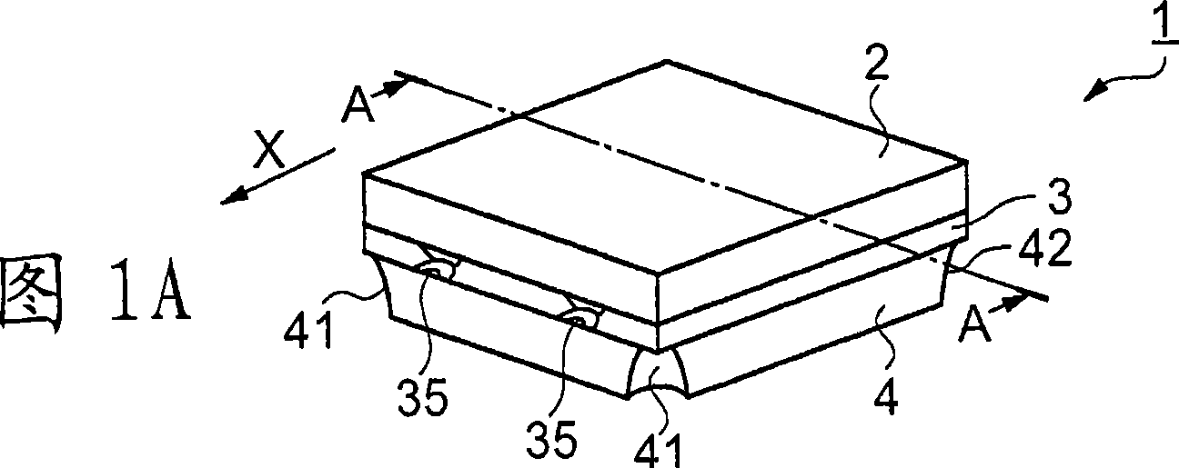
[0037] FIG. 1 shows a piezoelectric vibrator 1 in the present embodiment of the present invention.

[0038] FIG. 1A is a perspective view of a piezoelectric vibrator 1 , and FIG. 1B shows a cross-sectional view along line A-A of FIG. 1A .

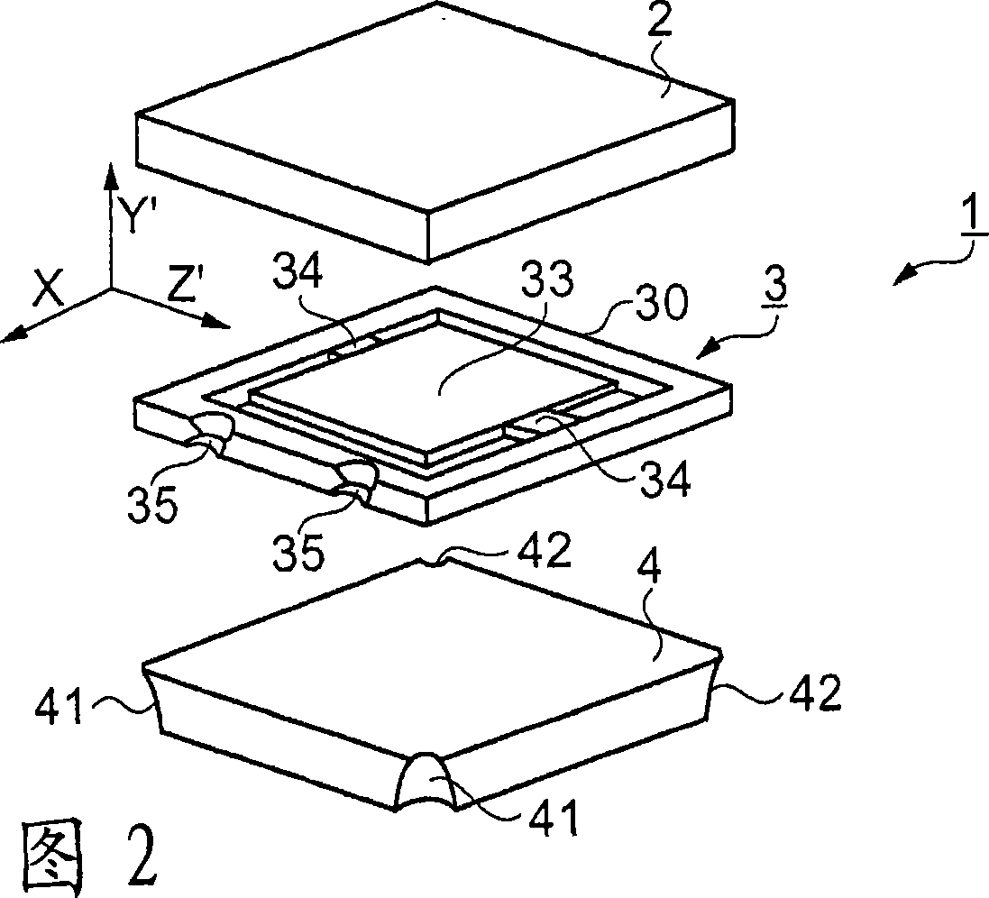
[0039]In addition, FIG. 2 shows an exploded perspective view of the piezoelectric vibrator 1 . The piezoelectric vibrator 1 has a cover substrate 2 , a vibrator substrate 3 , and a base substrate 4 .

[0040] FIG. 3A shows a plan view of the transducer substrate 3 viewed from the lid substrate 2 side, and FIG. 3B shows a plan view of the transducer substrate 3 viewed from the base substrate 4 side.

[0041] In FIG. 1A and FIG. 2 , the piezoelectric vibrator 1 is formed by overlapping the cover substrate 2 on the vibrator substrate 3 supported on the base substrate 4 . The vibrator substrate 3 is sandwiched between the cover substrate 2 and the base substrate 4 and bonded.

[0042] The base substrate 4 is a substantially rectangular plate...

no. 2 Embodiment approach

[0091] FIG. 8 shows two types of vibrator substrates 3 according to this embodiment of the present invention.

[0092] 8A is a plan view of the transducer substrate 3 viewed from the base substrate 4 side, and FIG. 8B is a plan view of another transducer substrate 3 viewed from the base substrate 4 side.

[0093] In FIG. 8A , the support portions 34 of the vibrating piece 33 are aligned on the side of the frame portion 30 on the side of the concave portion 35 . The vibrating piece 33 and the frame portion 30 are penetrated by the hollow 314 .

[0094] The second excitation electrode 32 is provided on the surface of the vibrator substrate 3 that faces the base substrate 4 . More specifically, it is provided on the vibrating piece 33 , one of the two support portions 34 , and the surface of the frame portion 30 facing the base substrate 4 . Here, the excitation electrode 32 is not provided in the vicinity of the concave portion 35 . The third electrode 36 is provided on the s...


PUM


Abstract

The invention provides a piezoelectric resonator and a method for manufacturing thereof. In order to obtain a smaller-sized piezoelectric resonator and method for manufacturing thereof, a first excitation electrode 31 formed on one surface of a vibration chip 33 is electrically connected to a third electrode 36 formed on the surface on which a second excitation electrode 32 is formed, via a recessed part 35 on the side surface of a resonator substrate 3. Therefore, the first excitation electrode 31 can be collected to the surface on which the second excitation electrode 32 is formed, and mounting on one surface can be performed. Furthermore, since the first excitation electrode 31 and a third electrode 36 are electrically connected to each other not via a through-hole but via the side surface, the resonator substrate 3 does not need any area to be penetrated and the resonator substrate 3 can be made small with respect to the vibration chip 33 of the same size. As a result, a small-sized piezoelectric vibrator can be obtained. Moreover, since the first excitation electrode 31 and the third electrode 36 are electrically connected via the recess 35, disconnection and discharge caused by contact from the outside can be reduced.

Description

technical field [0001] The present invention relates to a piezoelectric vibrator used in small electronic equipment and a manufacturing method thereof. Background technique [0002] Small electronic devices are required to be further miniaturized, and piezoelectric vibrators used in small electronic devices are also required to be miniaturized. [0003] Here, the larger the vibration area of ​​the vibrating piece used for the piezoelectric vibrator, the smaller the crystal impedance (CI) value and the easier it is to vibrate, so it is necessary to increase the vibration area as much as possible. Therefore, in order to reduce the size of the piezoelectric vibrator while securing the vibration area of ​​the vibrating reed, it is necessary to reduce the size of the package that accommodates the vibrating reed. In miniaturization of the package, it is necessary to improve the layout of electrodes provided on the package, and the like. [0004] For this reason, the following im...

Claims


Application Information

Patent Timeline
IPC IPC(8): H03H9/19H03H3/02
Inventor 土户健次
Owner TOYO TSUSHINKI
Learn More