Electrostatic generator
A technology of static electricity generation and static electricity, which is applied in induction generators and other directions to achieve the effect of improving the use effect, saving space and compact structure
- Summary
- Abstract
- Description
- Claims
- Application Information
AI Technical Summary
Problems solved by technology
Method used
Image
Examples
Embodiment 1
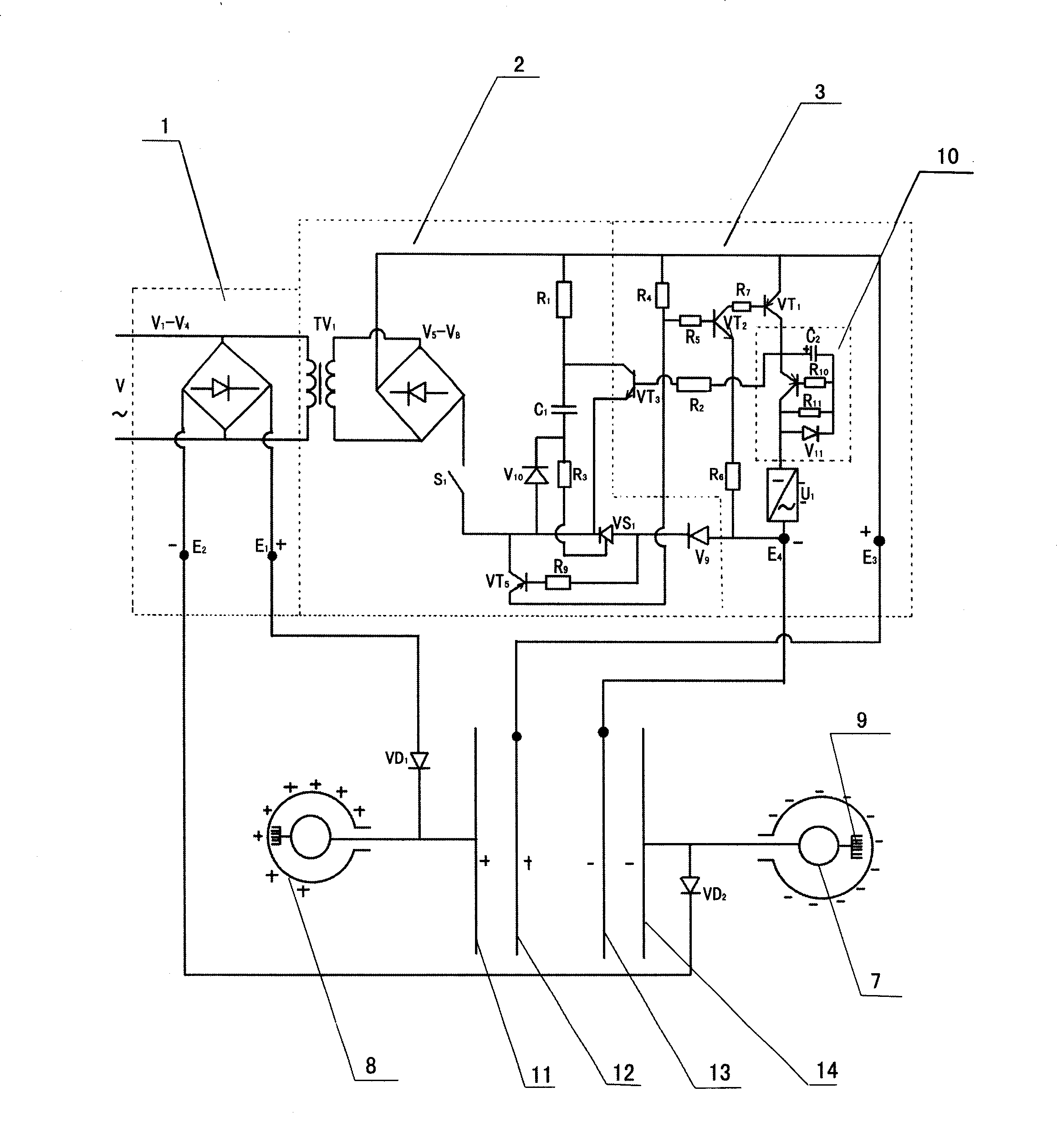
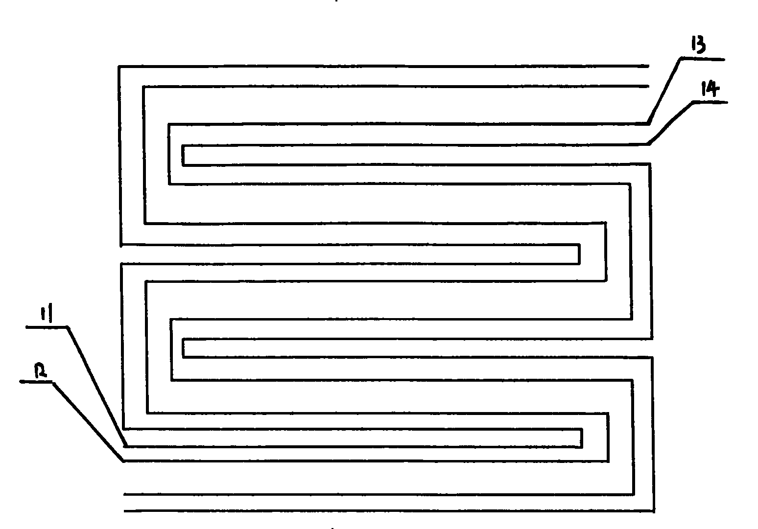
[0030] Embodiment one, in figure 1 and figure 2 Among them, the present invention is a kind of static electricity generation device, and it comprises static electricity generation part, current collecting device and input control part, and static electricity generation part comprises the conductor that is made up of the conductor layer that is insulated from each other of four layers, and conductor is respectively made of two layers of static electricity generation layer It consists of two layers of charge repelling layers, the static electricity generating layer is located in the outer layer, the charge repelling layer is located in the inner layer, a dielectric is provided between each layer, the polarity of the charging input end of the adjacent charge repelling layer and the static electricity generating layer is the same, and the conductor It is an S-shaped arrangement, and the input control part includes power supply, charging circuit I1, charging circuit II2 and disch...
Embodiment 2
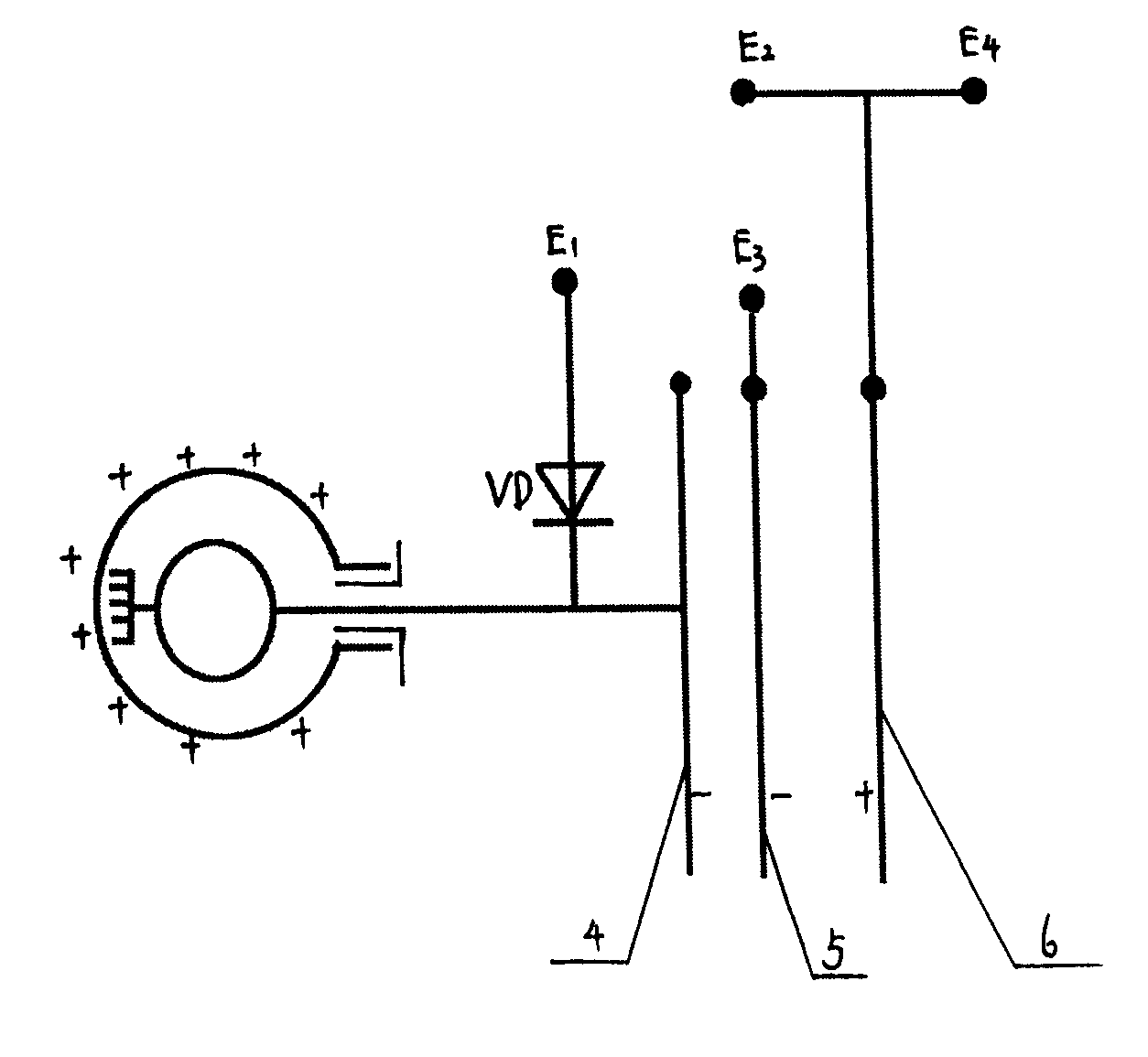
[0035] Example two, in image 3 Among them, its current collection generation part includes three layers, from left to right are the positive static electricity generation layer 4, the positive charge repulsion layer 5, the positive static electricity generation layer and the positive charge repulsion layer share the charging layer 6, and the three layers are S-shaped distribution In this embodiment, the common charging layer 6 can be used not only as a negative static electricity generation layer, but also as a negative charge repelling layer. The positive static electricity generation layer is connected to the inner ball 7 of the positive current collector ball, and the structure and working process of its input control part are the same as those in the first embodiment. The conductor is a three-layer conductor layer, and the measurement formula of the charging voltage of the two charging circuits:
[0036] V 1 ...
Embodiment 3
[0040] Embodiment three, in Figure 4 and Figure 5 Among them, the current collecting balls in this embodiment are two positive and one negative current collecting balls, both of which are equipped with current collecting generating parts, and each of the two static electricity generating parts has four conductor layers insulated from each other and arranged in a star shape , in the positive current collecting ball, from the outer ring to the inner ring in order: the outer ball 8 of the positive current collecting ball, the positive static electricity generation layer, the positive charge repulsion layer, the negative charge repulsion layer, the negative static electricity generation layer, and the negative current collection layer From the outer ring to the inside of the ball, there are negative current collector ball outer ball 8, negative static electricity generation layer, negative charge repulsion layer, positive charge repulsion layer, positive static electricity gener...
PUM
 Abstract
Description
Claims
Application Information
 - R&D Engineer
- R&D Manager
- IP Professional
- Industry Leading Data Capabilities
- Powerful AI technology
- Patent DNA Extraction
Browse by: Latest US Patents, China's latest patents, Technical Efficacy Thesaurus, Application Domain, Technology Topic, Popular Technical Reports.
© 2024 PatSnap. All rights reserved.Legal|Privacy policy|Modern Slavery Act Transparency Statement|Sitemap|About US| Contact US: help@patsnap.com


