Arrangement for amplifying a PWM input signal

A technology of PWM signal and input signal, which is applied in amplifiers, audio amplifiers, amplifier types, etc., and can solve the problem of reducing the dynamic range of pulse width modulation amplifiers, etc.

Inactive Publication Date: 2007-10-17
NXP BV
View PDF1 Cites 0 Cited by
  • Summary
  • Abstract
  • Description
  • Claims
  • Application Information

AI Technical Summary

Problems solved by technology

However, less steep edges reduce the maximum achievable pulse width modulation and thus the dynamic range of the amplifier

Method used


Image

  • Arrangement for amplifying a PWM input signal
  • Arrangement for amplifying a PWM input signal
  • Arrangement for amplifying a PWM input signal

Examples


Embodiment Construction

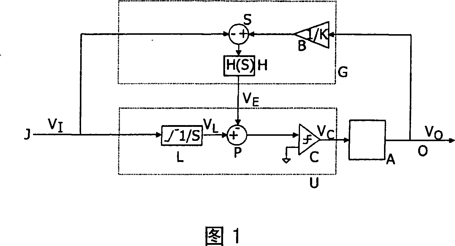
[0023] The prior art device of Figure 1 includes a PWM input signal V I is applied to input J. In this example, the input signal is an analog PWM signal. This signal is processed in a shaping unit U, in which a correction of the PWM input signal takes place, the operation of which is explained below. The output signal of the unit drives a class D output stage A whose output O may be coupled to one or more loudspeakers (not shown), for example through a standard class D low pass filter. To reduce the effect of amplitude and / or timing errors that occur in this output stage, the PWM output signal of amplifier A, V 0 Applied to the error correction signal generator G, where the output signal V is first attenuated by the attenuator B 0 , and then supplied to the subtractor S. In this subtractor, from the attenuated output signal V 0 Subtract the input signal V I . The difference between these two PWM signals is filtered in a low-pass filter H using a transfer function H(s) t...


PUM


Abstract

A pulse width modulation (PWM) amplifier comprises a feedback loop for reshaping the pulses of the PWM input signal to correct timing and amplitude errors in the class D output stage of the amplifier. The arrangement enhances the error correction by using a pulse width modulated triangle whose zero crossings substantially coincide with the edges of the PWM input signal. The triangle may be obtained by full integration of a modified PWM signal whose zero crossings lie in the middle of the pulses of the PWM input signal.

Description

technical field [0001] The invention relates to a device for amplifying a PWM input signal, said device comprising: a class D output stage; an error correction signal generator arranged to compare the PWM output signal of the class D output stage with the PWM input signal and to supply a source an error correction signal from the comparison; and shaping means arranged to receive the PWM input signal and the error correction signal, and supply the shaped PWM signal to the input of the class D output stage. Such a device is known from published international patent application WO98 / 44626. Background technique [0002] In the above-mentioned patent application, the error correction signal controls a shaping device in which the edges of the PWM input signal are shifted in order to compensate for amplitude and timing errors present in the class D output stage. For this purpose, prior art devices utilize limited integrators to generate sloped edges on incoming pulses. Subsequent...

Claims


Application Information

Patent Timeline
Patent Type & Authority Applications(China)
IPC IPC(8): H03F3/217
CPCH03F2200/393H03F3/217H03F2200/03
Inventor 彼德鲁斯·A·C·M·努伊金卢岑·L·A·H·多普
Owner NXP BV
Why Eureka
Try Eureka