
Apparatus for manufacturing corrugated sheets

A technology for manufacturing devices and corrugated plates, which is applied in the direction of noise reduction devices, exhaust devices, catalyst carriers, etc., and can solve the problems of increasing remaining catalyst fillet, increasing ventilation resistance, and reducing surface area.

Inactive Publication Date: 2007-10-17
CALSONIC KANSEI CORP
View PDF1 Cites 4 Cited by
  • Summary
  • Abstract
  • Description
  • Claims
  • Application Information

AI Technical Summary

Problems solved by technology

[0004] In the above-mentioned conventional manufacturing method, at the end of winding, there is a step in the corrugated plate wound in the last turn. If it is directly pressed into the casing, local deformation will be caused by the step at the end of winding.
Also, this deformation propagates toward the center, causing the inner shape to differ from the designed shape
In this way, when the internal shape is deformed, there is a problem that the residual catalyst fillet after the catalyst coating is increased, and the ventilation resistance is increased.
[0005] In addition, there is also the problem that the surface area per unit volume of the corrugated plate in contact with the gas will decrease after the catalyst is coated.

Method used


Image

  • Apparatus for manufacturing corrugated sheets
  • Apparatus for manufacturing corrugated sheets
  • Apparatus for manufacturing corrugated sheets

Examples


Embodiment Construction

[0020] Next, an embodiment of a corrugated plate manufacturing apparatus (hereinafter referred to as a corrugated plate manufacturing apparatus) according to the present embodiment will be described.

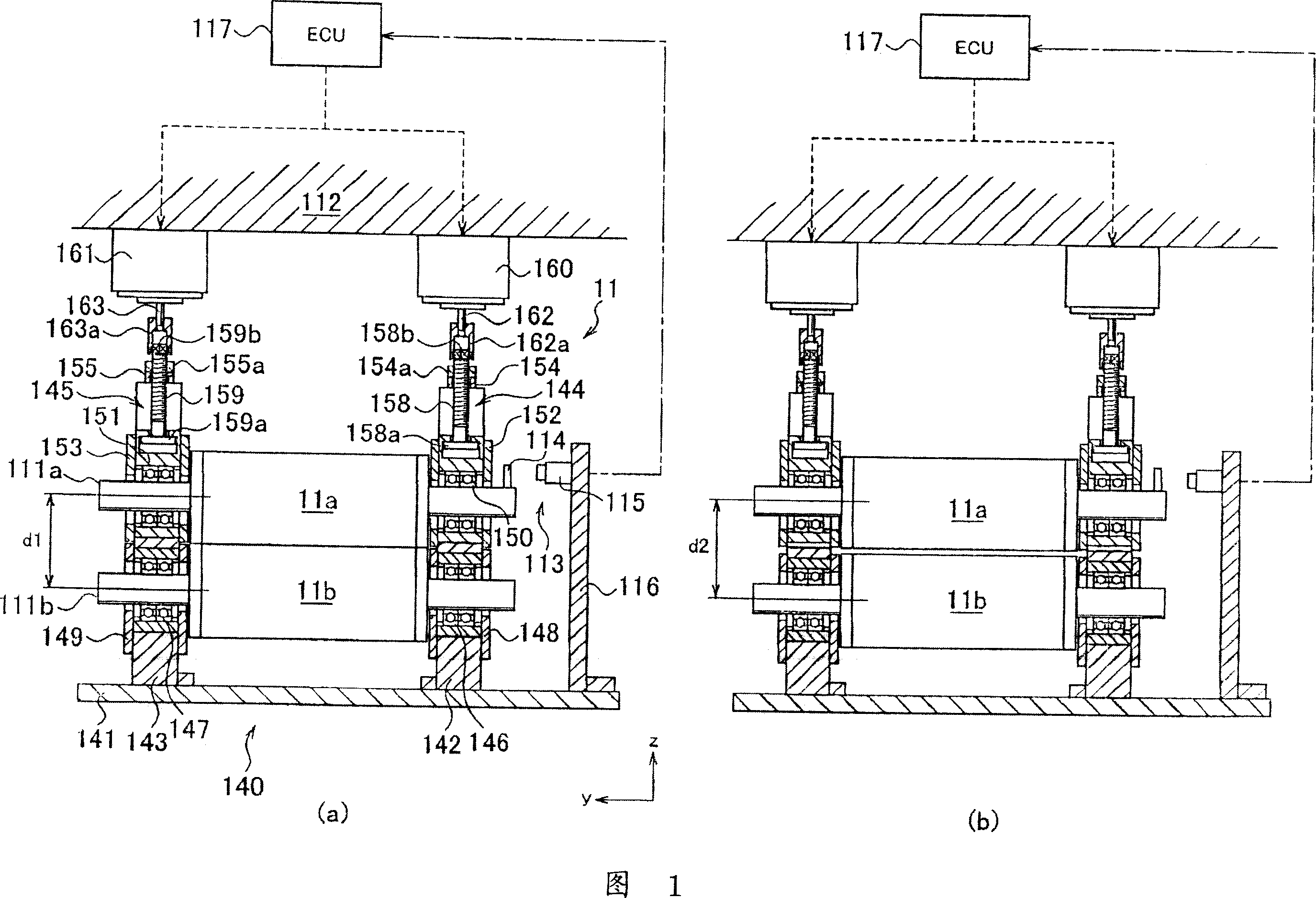
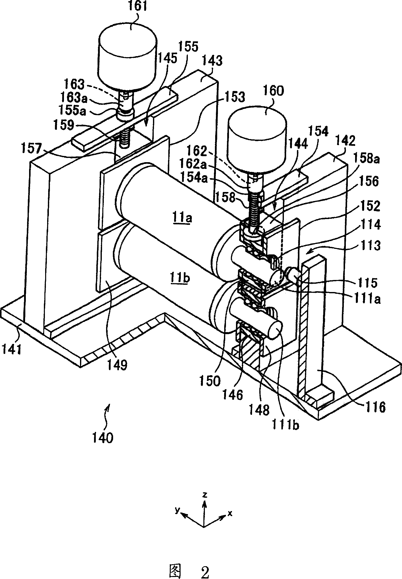
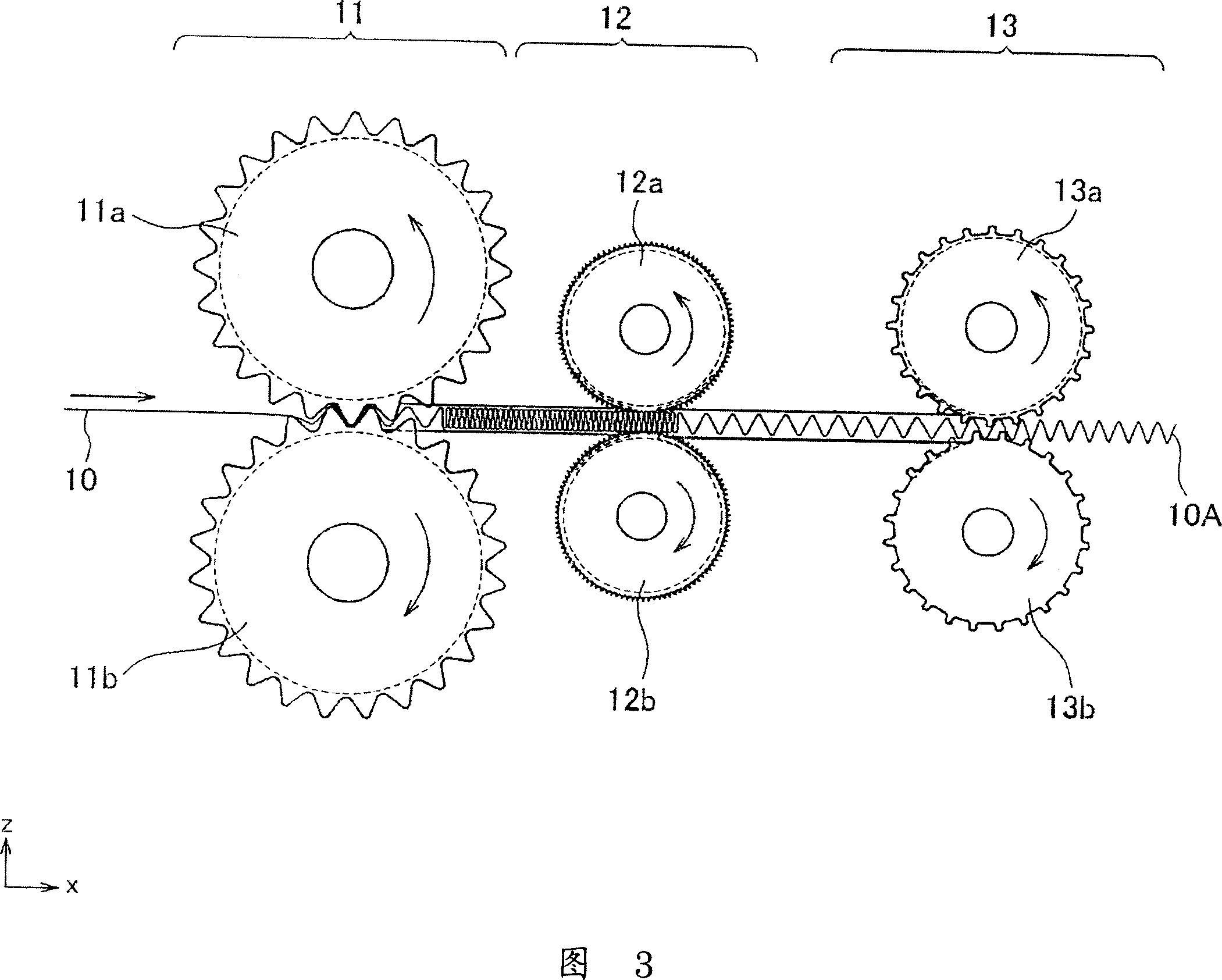
[0021] Fig. 1 (a), (b) is the cross-sectional view of the forming roll part which becomes the main part of the present invention, Fig. 2 is a partially cut-away perspective view of the forming roll, Fig. 3 is an overall structural view of a corrugated plate manufacturing device, Fig. 4 to Fig. 6 It is an enlarged view of each roller part.

[0022] First, the overall configuration of the corrugated plate manufacturing apparatus 100 will be described based on FIGS. 3 to 5 . As shown in FIG. 3 , the corrugated plate manufacturing apparatus 100 of the present embodiment includes a forming roll unit 11 , a shrinking roll unit 12 , and a fixing roll unit 13 .

[0023] In addition, although not shown in the figure, a supply roll for winding the strip-shaped corrugated plate material 1...


PUM


Abstract

The present invention provides an apparatus of manufacturing a corrugated sheet with which the generation of local deformation when a core is force-fitted into an outer jacket is prevented and purifying capacity is improved in a metallic carrier which is composed by winding around the corrugated sheet and a flat sheet. In an ECU 117, when the number of revolutions of forming rolls 11a, 11b reach the preset number r1 of revolutions, the center distance of the forming rolls 11a, 11b is taken as a second reference center distance d2 which is wider than the reference center distance d1 by driving motors 160, 161 and making unit holding frames 152, 153 gradually ascend. Thus, since the developed length of the corrugated sheet 10A to be formed is gradually shortened, the wave-height is also gradually lowered. When a corrugated sheet 2 and the flat sheet 3 are wound around, the wave-height in the end part of winding-around is gradually lowered and the generation of difference in level in the end part is prevented, the generation of the local deformation is prevented when the core is forced-fit into the cylindrical outer jacket 4.

Description

technical field [0001] The present invention relates to a corrugated plate which can be used for a metal carrier used for purifying exhaust gas discharged from an internal combustion engine of an automobile, and more particularly, to a manufacturing apparatus of a corrugated plate having a portion with a gradually decreasing wave height. Background technique [0002] In a vehicle having an internal combustion engine such as an automobile, a metal carrier is used as a catalyst device for removing harmful components contained in exhaust gas. Such a metal carrier is composed of a metal honeycomb core with a honeycomb cross section manufactured by laminating and winding a flat plate and a corrugated plate, and a metal shell for accommodating the metal honeycomb core. [0003] In the past, the manufacturing method of the metal honeycomb core body (hereinafter referred to simply as the core body) is to stack the corrugated plate and the front end of the flat plate, sandwich it in ...

Claims


Application Information

Patent Timeline
Patent Type & Authority Applications(China)
IPC IPC(8): B21D13/04B01D53/94B01J32/00B01J35/04F01N3/28
CPCF01N3/2814B21D13/04F01N2330/04
Inventor 金田照久
Owner CALSONIC KANSEI CORP
Learn More