
Plaiter structure

A cloth folding machine and cloth technology, applied in the direction of folder, folding thin material, laundry room device, etc., can solve the problems of uneconomical, unable to fold out cloth 40, unable to be effectively solved, etc., to achieve high cloth storage, large The effect of carrying space

Inactive Publication Date: 2007-10-10
PAI LUNG MACHINERY MILL CO LTD
View PDF0 Cites 11 Cited by
  • Summary
  • Abstract
  • Description
  • Claims
  • Application Information

AI Technical Summary

Problems solved by technology

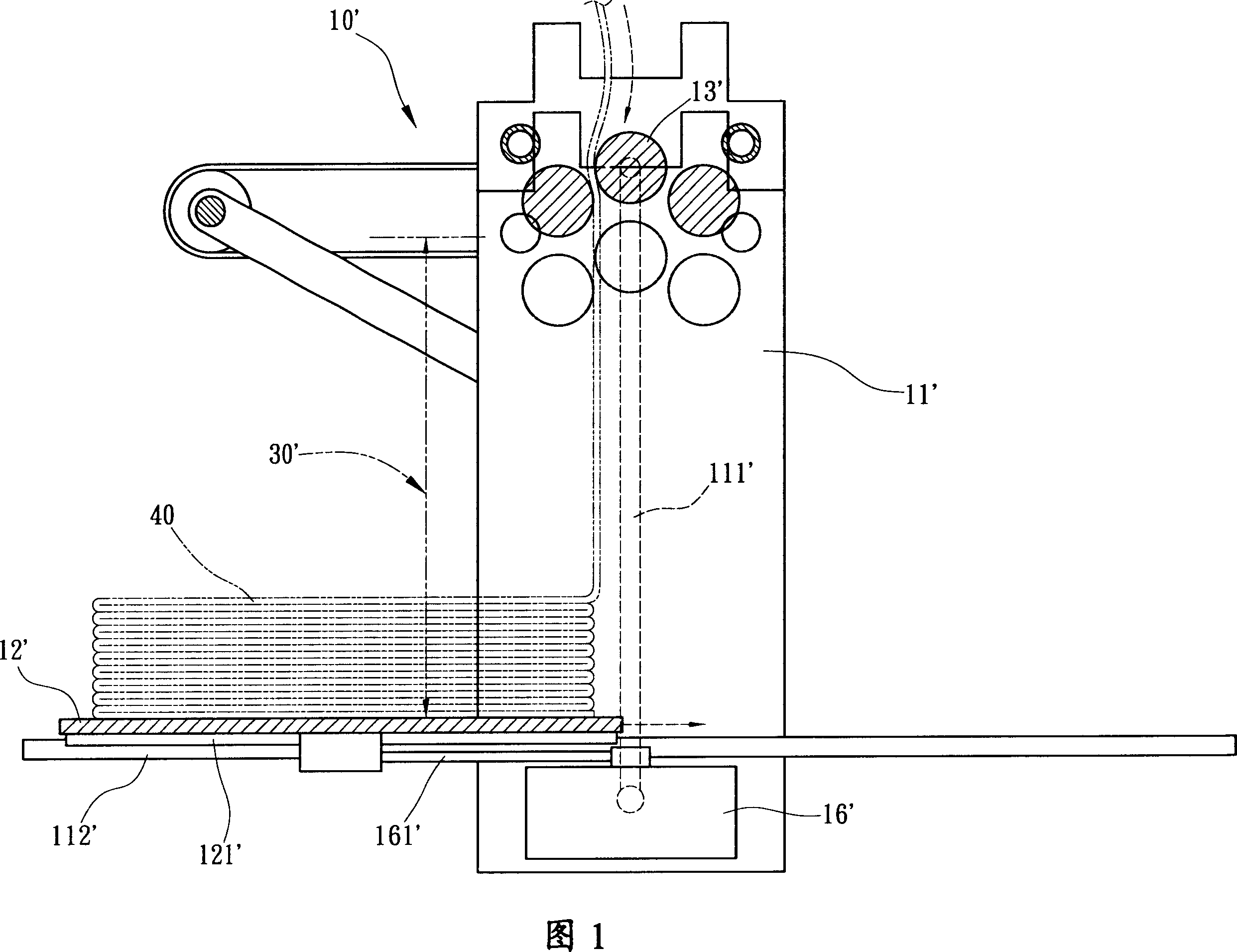
[0012] 2. Based on the above, if the folding bearing space 30' on the bearing seat 12' is to be increased, the side seat 11' must be increased upward, the transmission rod 111' lengthened, and the rolling rod 13' must be moved upward, so that The change will affect the shape of the connecting element (not shown) between the cloth folding machine 10' and the circular knitting machine, which must be redesigned, which is quite uneconomical
[0013] 3. In addition, because these known solutions all use the bearing 12' to slide back and forth horizontally on the slide rail 112', the size of the folded cloth must be less than half the length of the slide rail 112', that is to say , these known cloth folding machines 10' can only fold out half-sized cloth 40, but cannot fold out full-width cloth 40 as long as the slide rail 112'
[0014] The various problems of the above-mentioned known folding machines are problems that have existed in the industry for a long time, but they have not been effectively solved. Therefore, it is an urgent task for the industry to solve the above-mentioned problems.

Method used


Image

  • Plaiter structure
  • Plaiter structure
  • Plaiter structure

Examples


Embodiment Construction

[0022] Relevant preferred embodiment of the present invention and technical content, cooperate accompanying drawing to illustrate as follows now:

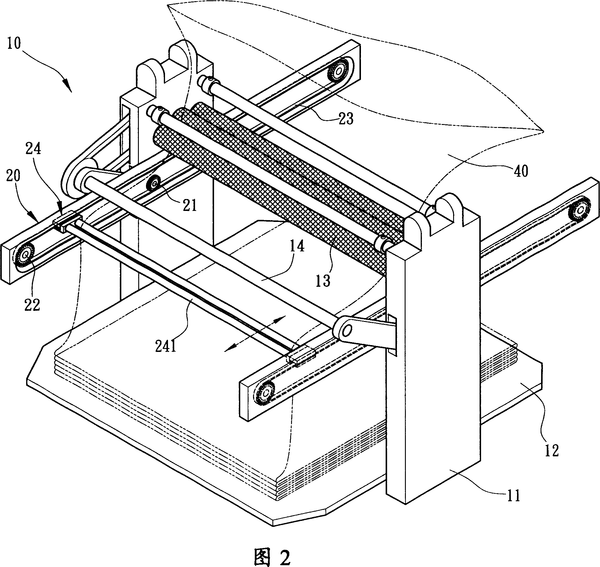
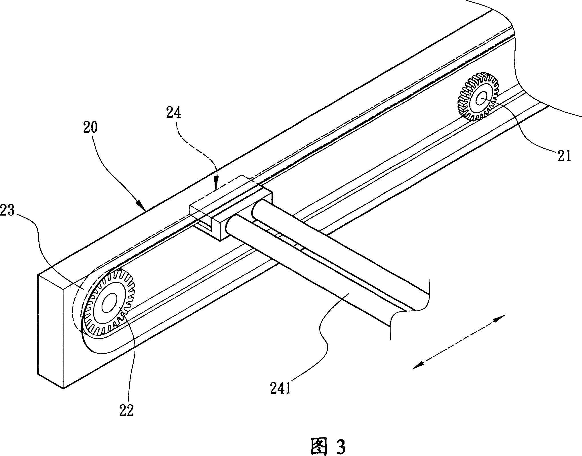
[0023] Please refer to FIG. 2 and FIG. 3 , which are respectively a three-dimensional schematic diagram of the structure of the fabric folding machine and a three-dimensional schematic diagram of the partial appearance of the fabric folding unit of the present invention. The structure of the cloth folding machine 10 of the present invention is applied to the folding mechanical structure of the cloth 40 woven by a circular knitting machine (not shown in the figure), the cloth folding machine 10 has a seat 12 that can carry the cloth 40, and The two ends of this bearing seat 12 are fixedly connected with the bottom ends of the two side seats 11, and at the upper end between the two side seats 11, there are many pieces of cloth 40 that can be flattened by the circular knitting machine for The cloth rolling rod 13 collected, in additio...


PUM


Abstract

The present invention discloses a cloth-folding machine structure for circular knitter. Said cloth-folding machine structure includes the following several portions: a bearing base seat for bearing cloth, several cloth-spreading rollers and a cloth-folding unit. Said invention also provides the concrete structure of above-mentioned every portion, and also provides the operation method of said cloth-folding machine structure.

Description

technical field [0001] The invention relates to a cloth folding structure, in particular to a cloth folding machine structure suitable for synchronously collecting cloth woven by a circular knitting machine. Background technique [0002] At present, the cloth folding machines used in the general industry are almost all changed or added to the cloth folding machine structure used in the circular knitting machine to fold the cloth. In this way, it can meet the universality and The product value of multifunctionality; now regarding the technical field of the present invention, three known patents related to the cloth folding machine for collecting cloth by the circular knitting machine are retrieved as follows: [0003] 1. China Taiwan Patent Publication No. 00280327 "Folding Machine" Utility Model Patent, hereinafter referred to as "Prior Art 1". [0004] 2. The utility model patent of "Structure Improvement of Cloth Folding Machine" in Taiwan Patent Announcement No. 00441612...

Claims


Application Information

Patent Timeline
Patent Type & Authority Applications(China)
IPC IPC(8): D06F89/00B65H45/04
Inventor 陈万益
Owner PAI LUNG MACHINERY MILL CO LTD
Learn More