
Gas insulation open-close device

A gas-insulated opening and closing technology, which is applied in switchgear, switchgear setting, electrical components, etc., can solve the problem of far-reaching miniaturization effect, and achieve the effect of reducing the floor area, improving maintenance, and reducing the depth dimension.

Inactive Publication Date: 2007-10-03
KK TOSHIBA
View PDF1 Cites 9 Cited by
  • Summary
  • Abstract
  • Description
  • Claims
  • Application Information

AI Technical Summary

Problems solved by technology

That's a long way from the minification effect that the proposal is trying to address.

Method used


Image

  • Gas insulation open-close device
  • Gas insulation open-close device
  • Gas insulation open-close device

Examples


Embodiment Construction

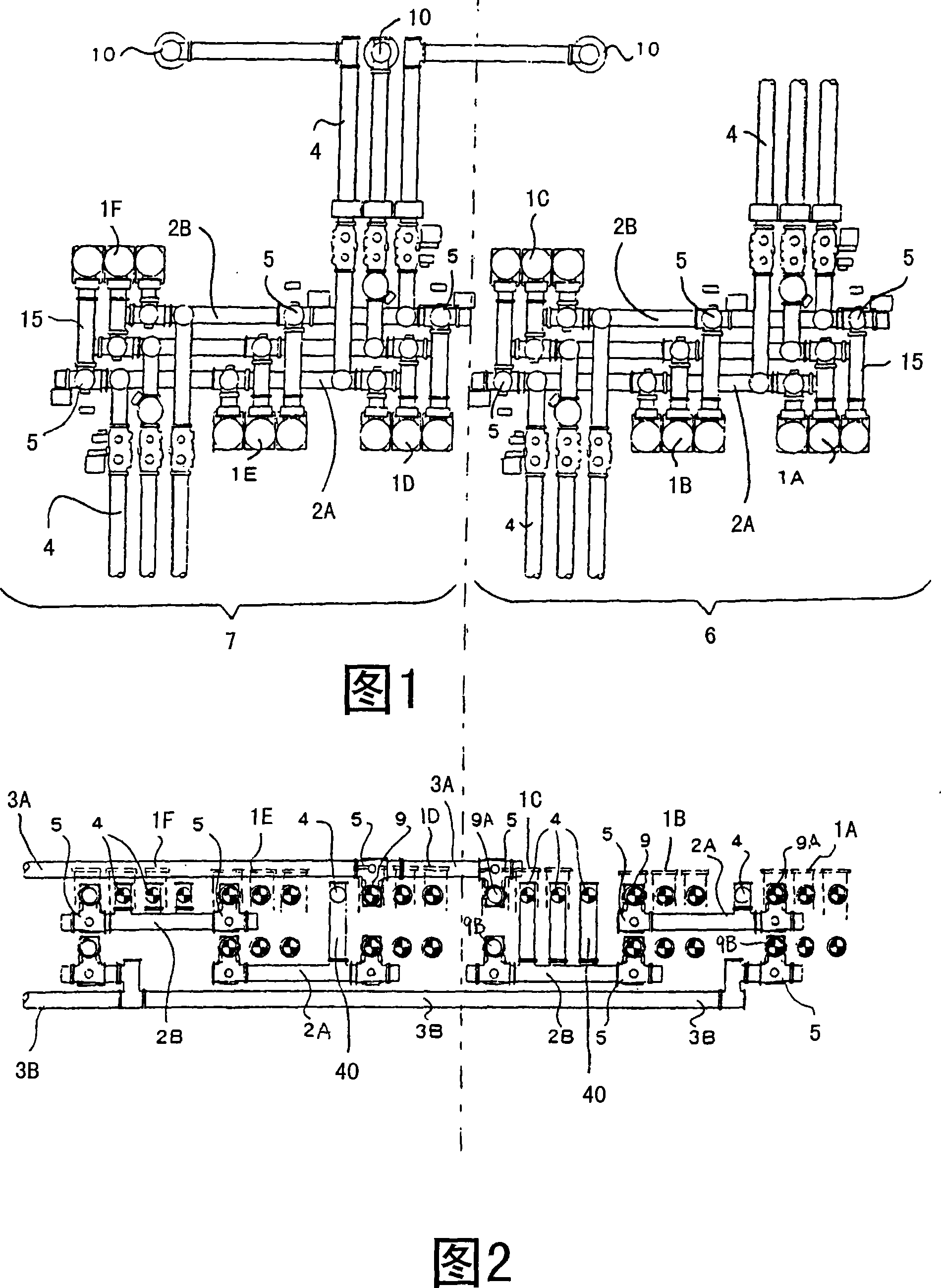
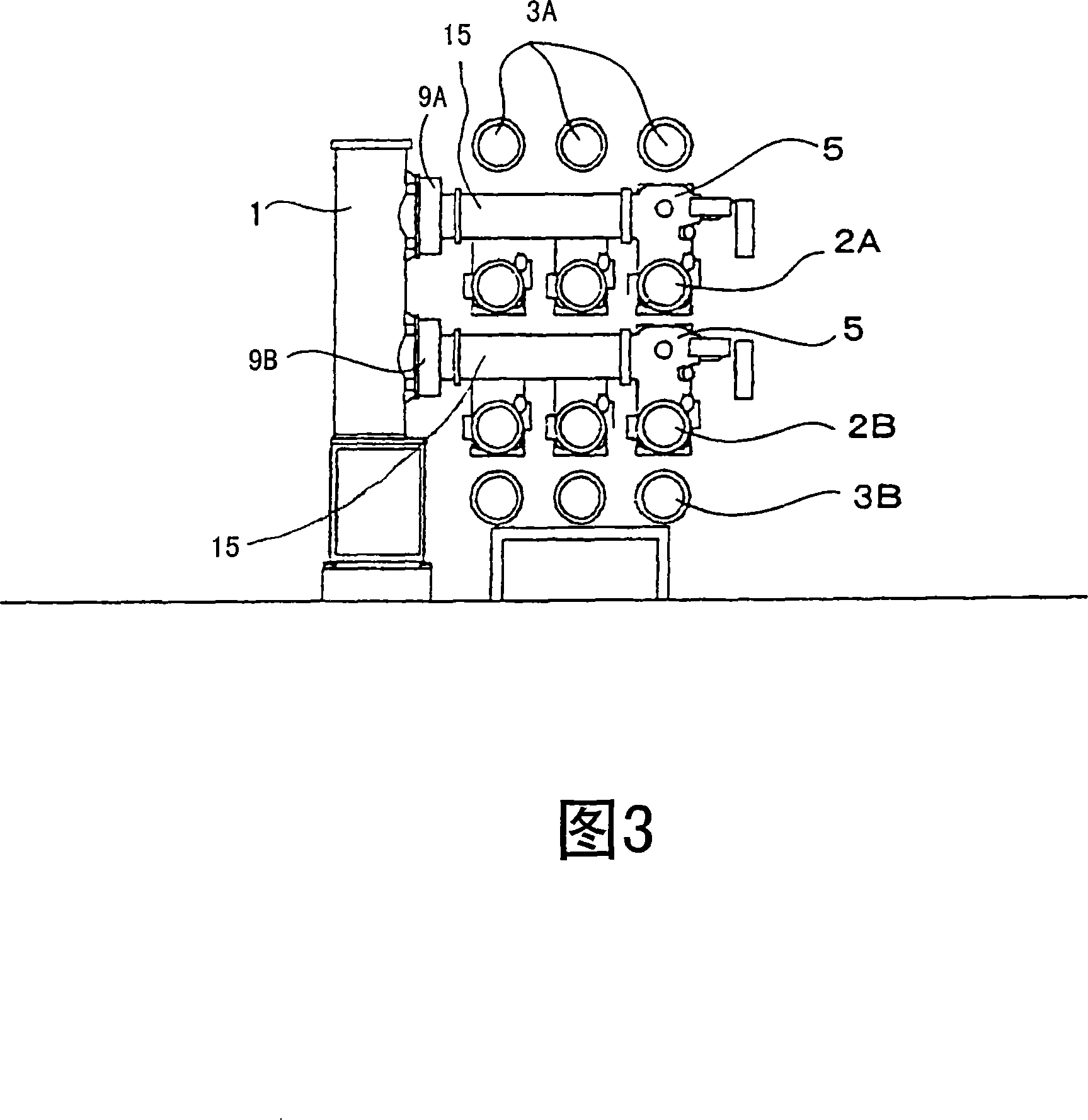
[0029] Next, a first embodiment of the present invention will be specifically described with reference to FIGS. 1 to 4 . That is, FIG. 1 is a plan view of the present embodiment, FIG. 2 is a front view showing a part of the circuit breaker and the connecting main bus bar between lines, and FIG. 3 is a side view showing the relationship between the vertical circuit breaker part and the main bus bar, Figure 4 is a single-line wiring diagram. In addition, the same reference numerals are assigned to the same components as those in the conventional gas insulated switchgear shown in FIG. 5 for description.

[0030] (1) Structure of Embodiment

[0031] As shown in Fig. 1, the first and second lines 6 and 7 are composed of three single-phase busbars arranged in parallel to each other to form three phases, and the busbars 2A and 2B are connected in the line, and three circuit breakers 1A arranged at approximately equal intervals , 1B, 1C, and 1D, 1E, 1F are connected in series. Furt...


PUM


Abstract

The invention provides a GIS effectively equiped with device and busbar, in order to reduce the area of applying ground and busbar length, and enhance the maintenance of breaker and recovery efficiency. The circuit in-cinnection busbar, eduction busbar, vertical breaker, and circuit among-cinnection main busbar are made by single phase device. The circuit in-cinnection busbar, vertical breaker and circuit among-cinnection main busbar make triphase divided busbar parallelly allocate on the same plane. The circuit in-cinnection busbar and circuit among-cinnection main busbar coincide up and down to make the mian axis of busbar of each phase slightly overlap at the same direction and on the same plane. The eduction busbar is coincident allocated at the direction crossed with the main axis of the circuit in-cinnection busbar and circuit among-cinnection main busbar. The vertical breaker is set beside the circuit in-cinnection busbar and circuit among-cinnection main busbar, and the orientation thereof is paralleled with the main axis of the circuit in-cinnection busbar and circuit among-cinnection main busbar.

Description

technical field [0001] The present invention relates to a gas insulated switchgear. As a bus connection method for an electrical circuit in an electric station such as a substation, there is a 11 / 2 circuit breaker system in which three circuit breakers are arranged in series between main bus bars between lines. layout composition. Background technique [0002] Generally, in an electric station to which a gas insulated switchgear (hereinafter abbreviated as GIS) is applied, when a 11 / 2 circuit breaker type layout configuration is performed, as shown in FIG. Connect multiple lines (in this example, for the sake of illustration, the number of lines is 2 lines, line 6 and line 7), and on each line 6 and 7, three vertical circuit breakers 1A~1C and 1D~1F pass The isolating switches 5 arranged on both sides of each circuit breaker are electrically connected in series with the connecting busbars 2A and 2B in the line respectively. By adopting the 11 / 2 circuit breaker method, it b...

Claims


Application Information

Patent Timeline
Patent Type & Authority Applications(China)
IPC IPC(8): H02B1/20
CPCH02B1/20H02B13/035
Inventor 小原礼二池下宽
Owner KK TOSHIBA
Learn More