Compact 1XN light power shunt

A splitter and optical power technology, applied in the field of integrated optoelectronics, can solve the problems of lengthening device size, increasing loss, uneven power distribution, etc., and achieve the effect of balanced output power and reduced size

Inactive Publication Date: 2007-10-03
SOUTHEAST UNIV
View PDF0 Cites 9 Cited by
  • Summary
  • Abstract
  • Description
  • Claims
  • Application Information

AI Technical Summary

Problems solved by technology

When the planar light wave optical path realizes T-shaped splitting and 90° turning, the loss will be greatly increased due to the large-angle bending. To reduce the loss, it is necessary to adopt a longitudinally variable structure and increase the size of the device.
In addition, some errors are inevitably introduced in the processing and production, resulting in uneven power distribution

Method used


Image

  • Compact 1XN light power shunt
  • Compact 1XN light power shunt
  • Compact 1XN light power shunt

Examples


Embodiment Construction

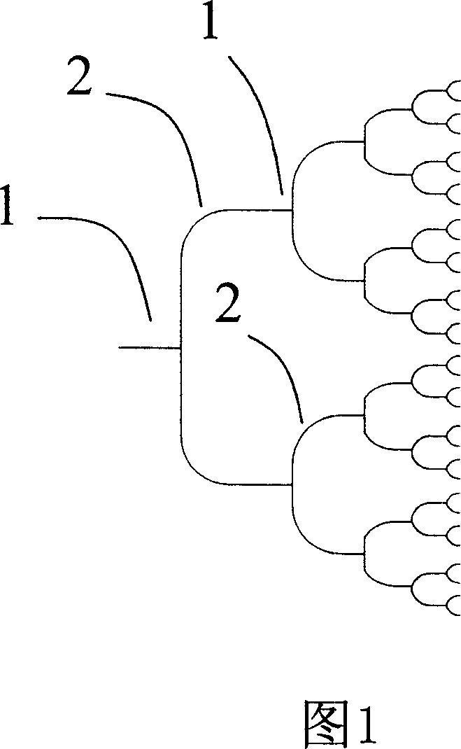
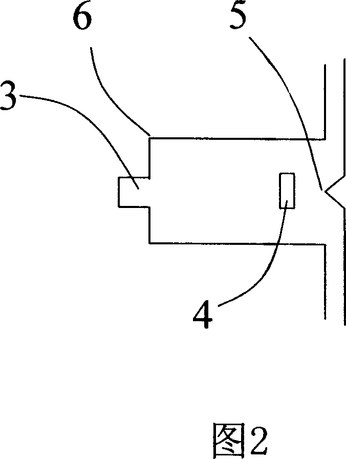
[0019] Referring to Fig. 1 and Fig. 2, a compact 1×N optical power splitter includes: N T-type splitters 1, N being a natural number greater than or equal to 2, as the T-type splitter of the previous stage The output ends are respectively connected to the input ends of the T-type splitter of the latter stage, which is characterized in that the T-type splitter 1 includes a multi-mode interference waveguide 6, and one end of the multi-mode interference waveguide 6 is provided as a T-type The single-mode incident waveguide 3 at the input end of the splitter is provided with a V-shaped groove 5 on the output end waveguide of the multi-mode interference waveguide 6, and the two output waveguides separated by the V-shaped groove 5 are used as the T-shaped splitter 2 an output end, and an optical power modulation module 4 is arranged on the multimode interference waveguide 6 . The above-mentioned optical power modulation module can adopt the modules disclosed in the prior art, for ex...


PUM


Abstract

The present invention belongs to the field of integrated photoelectronic technology, and is especially one kind of 1xN light power shunt with low loss, small size and homogeneous power output. The 1xN light power shunt includes N cascade T-shaped shunts, and each of the T-shaped shunts includes one multimode interference waveguide, one monomode incident waveguide serving as the input of T-shaped shunt, one output waveguide divided with one V-groove into two sections serving as two outputs of the T-shaped shunt, and one light power modulating module.

Description

technical field [0001] The invention belongs to the technical field of integrated optoelectronics, and relates to a new type of passive planar light wave optical circuit device, in particular to a compact 1×N optical power splitter. Background technique [0002] The optical power splitter (hereinafter referred to as the power splitter) is an indispensable device unit for connecting the end users of the trunk road of the optical fiber communication network, and has been widely used in the fiber-to-the-home passive optical network; and with the optical interconnection in For applications in high-performance computers, power dividers are also one of the necessary devices. Fiber optic splitters have uneven power distribution and large volume, making it difficult to apply in occasions that require a large number of ports. Planar light wave optical circuit devices are based on microelectronic technology, which can conveniently realize functions such as large port number and unifo...

Claims


Application Information

Patent Timeline
Patent Type & Authority Applications(China)
IPC IPC(8): G02B6/28G02B6/125H04B10/12
Inventor 孙小菡于兵
Owner SOUTHEAST UNIV
Why Eureka
Try Eureka