
Lamp devices for vehicles

A technology for vehicles and lamps, which is applied to bicycle accessories, transportation and packaging, optical signals, etc. It can solve the problems that have not been disclosed or implied, and achieve the effects of shortening the positioning protrusions, improving the sense of luxury, and preventing partial loads

Inactive Publication Date: 2010-08-11
HONDA MOTOR CO LTD
View PDF1 Cites 0 Cited by
  • Summary
  • Abstract
  • Description
  • Claims
  • Application Information

AI Technical Summary

Problems solved by technology

[0005] However, in Patent Document 1, there is no disclosure or hint about a method of imparting continuity to the appearance by accurately and reliably combining the lighting device at a predetermined position of the enclosure. For example, although the direction indicator of the enclosure It is not obvious when the mounting surface is flat, but when the mounting surface protrudes, if the position of the mounting surface deviates from the direction indicator, the deviation in appearance will be obvious

Method used


Image

  • Lamp devices for vehicles
  • Lamp devices for vehicles
  • Lamp devices for vehicles

Examples


Embodiment Construction

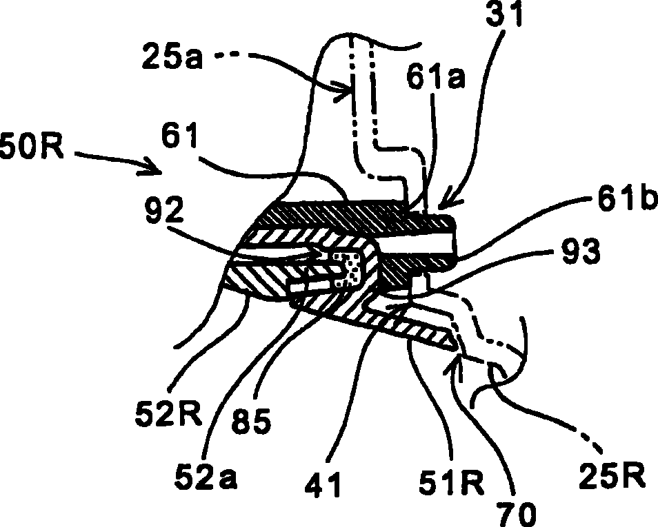
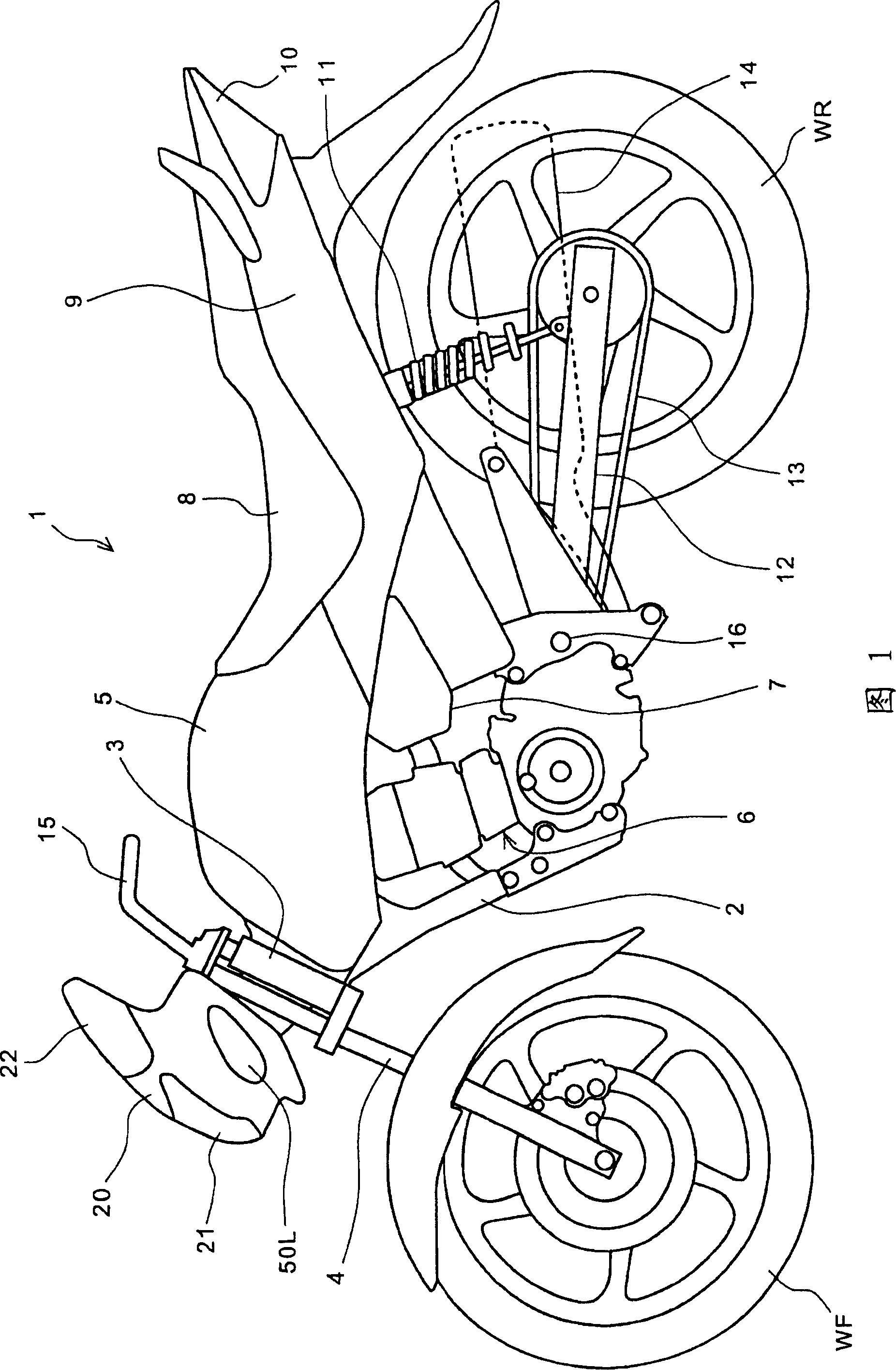
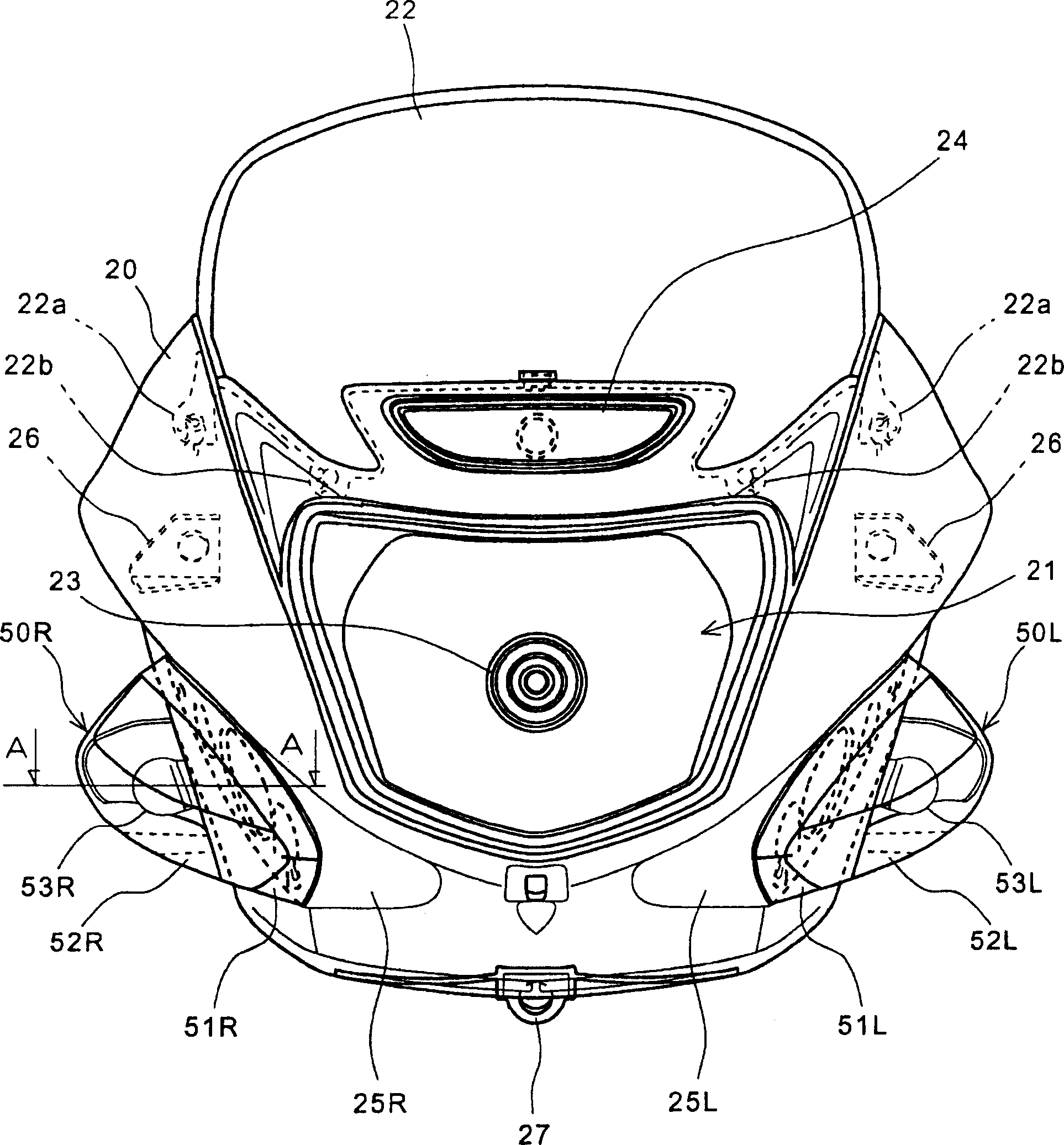
[0040] Hereinafter, preferred embodiments of the present invention will be described in detail with reference to the drawings. FIG. 1 is a side view of a motorcycle 1 to which a vehicle lighting device according to an embodiment of the present invention is applied. A head pipe 3 pivotally supporting a pair of left and right front forks 4 , 4 is joined to the front side of a frame 2 of the motorcycle 1 . The front wheel WF is rotatably pivotally supported on the lower ends of the front forks 4 , 4 steerable by the tiller handle 15 . An engine 6 as a driving source is suspended below the vehicle frame 2 . The engine 6 is operated by combustion of a mixture of air and fuel sucked in through the air cleaner 7 , and exhaust gas is discharged from a muffler 14 attached to the rear side of the vehicle body. The rotational driving force of the engine 6 is transmitted to the rear wheels WR through a drive chain 13 . The swing arm 12 rotatably supporting the rear wheel WR is suspende...


PUM


Abstract

The invention provides a luminaire device for vehicle, which can accurately install luminaire device on the preset position of the trunk. The indicator (50R) houses bulb between the lens (52R) and matrix part (51R) and performs mounting from the surface side of the front surface and the lug (61) for positioning formed surrounding the lug for binding set on the back of the matrix part (51R). A step part (61a) connecting with vertical face (41) of the mounting surface (25a) is installed on the lug (61) for positioning. After clipping the insertion part (61b) into the mounting surface (25a), theposition relative to front surface is accurately and reliably performed to make the protruding portion (25R) coplane with the bonding wire (70) of the matrix part (51R). The lug (61) for positioning is formed in manner of partly overlying with the banquette (93) on the back of the clipping groove (92) of the clipping lens (52R), thus the length of the lug (61) for positioning can be reduced.

Description

technical field [0001] The present invention relates to a lighting device for a vehicle, and more particularly, provides a lighting device for a vehicle that can be accurately installed at a predetermined position provided on an enclosure. Background technique [0002] Conventionally, there is known a vehicle in which a lighting device such as a blinker is embedded in an enclosure that protects occupants from traveling wind. [0003] Patent Document 1 discloses a flasher device for a motorcycle with a structure in which the blinker (strobe) covers the base member housing the bulb with a lens, and when the blinker is mounted on the left and right sides of the enclosure, the lights of the bulb are turned on and off. The socket portion protrudes from the back side of the base member, and is inserted into the through hole formed on the side of the enclosure when the blinker is attached. According to this device, the overall height of the blinker protruding from the surface of t...

Claims


Application Information

Patent Timeline
Patent Type & Authority Patents(China)
IPC IPC(8): B62J6/00
Inventor 山手直之松浦弘明
Owner HONDA MOTOR CO LTD
Learn More