Electronic shedding device of jacquard loom
A technology of opening device and jacquard machine, applied in the direction of jacquard machine, textile, textile and papermaking, etc., can solve the problems of damage to main parts of loom, increase of power consumption of jacquard machine, increase of installation height of jacquard machine, etc. The effect of linkage mechanism, simple mechanical structure and stable operation
- Summary
- Abstract
- Description
- Claims
- Application Information
AI Technical Summary
Problems solved by technology
Method used
Image
Examples
Embodiment 1
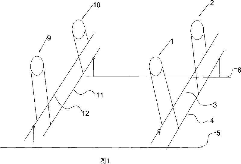
[0025] The electronic shedding device of the jacquard machine as shown in accompanying drawing 1, comprises two groups of lifting mechanisms, and one group of lifting mechanism consists of the lifting beam 11 and the lifting beam 4 on both sides and is connected between the lifting beam 11 and the lifting beam. A plurality of lifting knives 6 between the beams 4 are formed (only one lifting knife is drawn in the figure), and another group of lifting knives mechanism is composed of the lifting knife beams 12 and the lifting knife beams 3 on both sides and connected between the two lifting knives. A plurality of lifting knives 5 are formed between the beams (only one lifting knife is drawn in the figure), and transmission mechanisms are arranged on the two lifting knife beams on the same side, including transmission mechanism 1, transmission mechanism 2, transmission mechanism 9 and Transmission mechanism 10, each transmission mechanism is made up of gears and chains arranged on ...
Embodiment 2
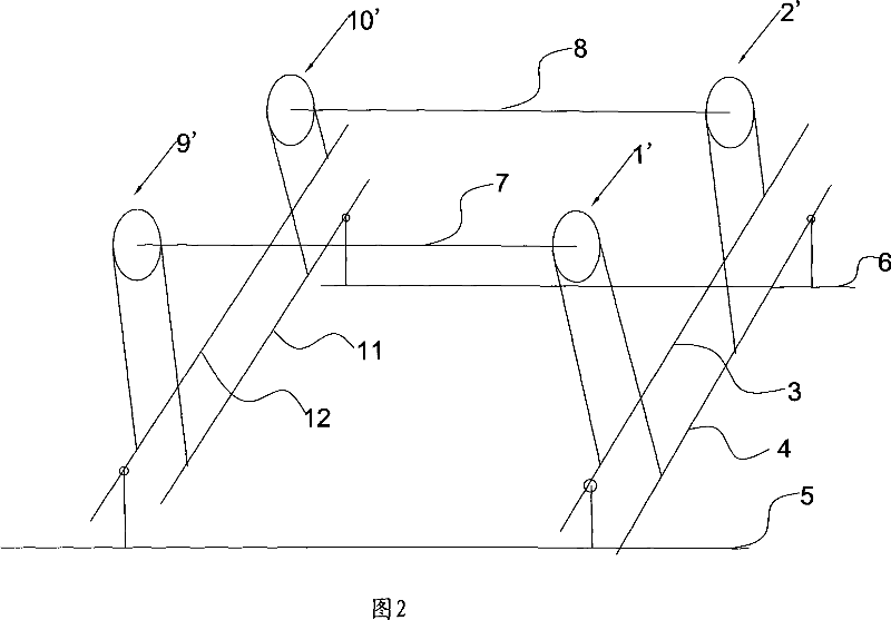
[0030] The structure of embodiment two is basically the same as that of embodiment one, the difference lies in the transmission mechanism, as shown in Figure 2, transmission mechanism 1 ' and transmission mechanism 9 ' carry out transmission through transmission shaft 7, transmission mechanism 2 ' and transmission mechanism 10 'Transmission is carried out through the transmission shaft 8, that is, in this specific embodiment, the transmission mechanism 1' and the transmission mechanism 2' can be used as the driving side, and the transmission mechanism 9' and the transmission mechanism 10' can be used as the driven side, so only two The motor described in the first embodiment can drive the transmission mechanism 1' and the transmission mechanism 2' respectively. The four transmission mechanisms can still be selected from the combination of gears and chains. The connection methods are the same, so I won’t go into details here. This kind of mechanism can save two motors, but the p...
Embodiment 3
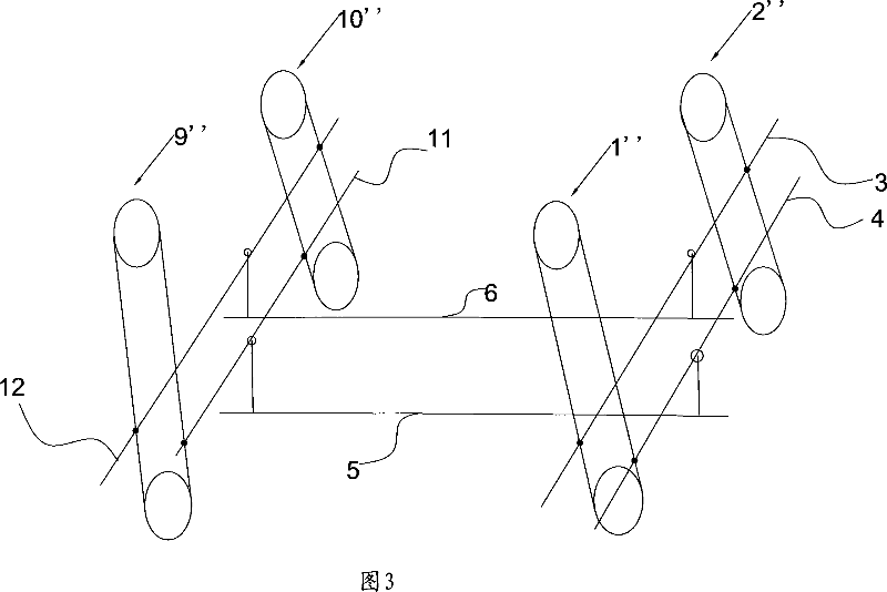
[0033] The structure of embodiment three is basically the same as that of embodiment one, and the difference lies in the transmission mechanism. As shown in accompanying drawing 3, transmission mechanism 1 ", transmission mechanism 2 ", transmission mechanism 9 " and transmission mechanism 10 " are belt transmission mechanisms, Each transmission mechanism includes a driving wheel, a driven wheel, and a timing belt tensioned between the driving wheel and the driven wheel. The connection mode of the knife lifting mechanism is the same as that in Embodiment 1, so it will not be repeated here. Wherein the drive wheels are respectively connected with the output ends of the motors (shown in the figure) described in Embodiment 1, and the two lifting beams on the same side are respectively connected with the synchronous belts moving in the opposite direction, so that when the angle of the motor output The displacement makes the driving wheel rotate forward or reverse at a certain angle...
PUM
 Abstract
Description
Claims
Application Information
 - Generate Ideas
- Intellectual Property
- Life Sciences
- Materials
- Tech Scout
- Unparalleled Data Quality
- Higher Quality Content
- 60% Fewer Hallucinations
Browse by: Latest US Patents, China's latest patents, Technical Efficacy Thesaurus, Application Domain, Technology Topic, Popular Technical Reports.
© 2025 PatSnap. All rights reserved.Legal|Privacy policy|Modern Slavery Act Transparency Statement|Sitemap|About US| Contact US: help@patsnap.com


