
1xn dynamic light wavelength router based on the micro-loop

A technology of optical wavelength and router, which is applied in the field of optical communication, can solve the problems of complex control module, complex structure, and large volume, and achieve the effect of large extinction ratio, small size, and high quality factor

Inactive Publication Date: 2007-09-12
ZHEJIANG UNIV
View PDF3 Cites 15 Cited by
  • Summary
  • Abstract
  • Description
  • Claims
  • Application Information

AI Technical Summary

Problems solved by technology

Patent CN1255995C proposes an all-optical wavelength routing cross module, which uses a demultiplexer, an optical space switch matrix, and a multiplexer to realize dynamic optical wavelength switching, but the structure is complex and the volume is large; The wavelength selection router implements wavelength routing through equal ratio cascading, but the control module is complicated and the loss is large; the patent US6195187B1 adopts a matrix structure as a whole to realize the multi-wavelength routing function, and the nodes adopt a double micro-ring structure, the structure is complex, and the control module is complicated

Method used


Image

  • 1xn dynamic light wavelength router based on the micro-loop
  • 1xn dynamic light wavelength router based on the micro-loop
  • 1xn dynamic light wavelength router based on the micro-loop

Examples


Embodiment Construction

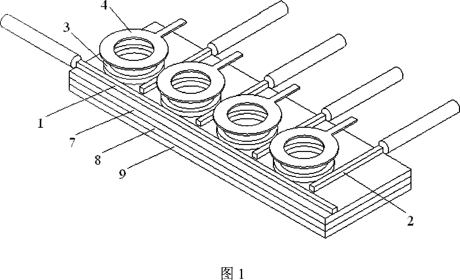
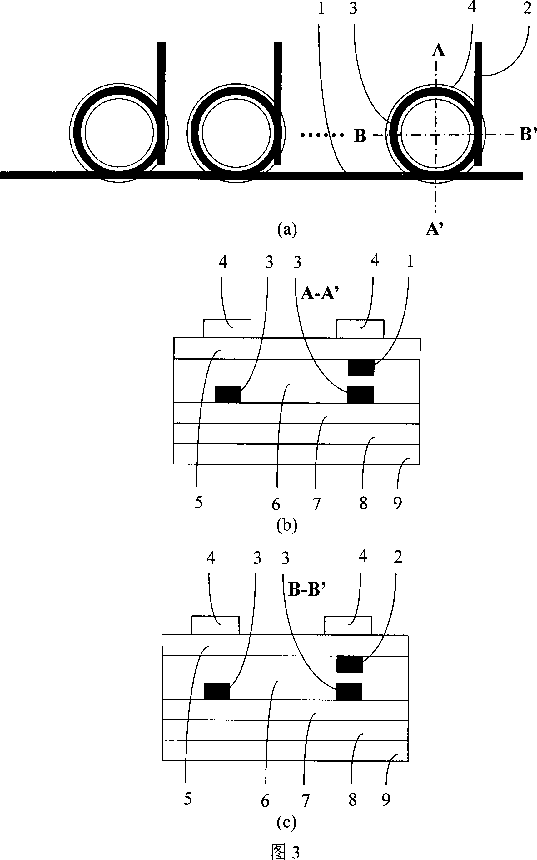
[0029] As shown in Figure 1 and Figure 2, the first structure of the present invention includes an input waveguide 1, an output waveguide 2, a microring 3, an upper electrode 4, an upper cladding layer 5, a core layer 6, a lower cladding layer 7, a lower electrode 8, Substrate9. The core layer 6 is provided with an input waveguide 1, N output waveguides 2 equally distributed and N microrings 3 equally distributed, the N microrings 3 are respectively adjacent to the respective output waveguides 2, and the upper cladding layer 5 N ring-shaped upper electrodes 4 corresponding to N microrings 3 are arranged on it, and N microrings 3 are arranged in sequence along the direction of input waveguide 1 , and N output waveguides 2 are perpendicular to and do not intersect with input waveguide 1 . The input waveguide 1, N output waveguides 2, and N microrings 3 are arranged in the same core layer plane. N optical signals of different wavelengths are input from the input waveguide 1, and...


PUM


Abstract

The invention discloses a kind of dynamic optical wavelength router which is based on 1 * N of annulet. Input waveguide in a sandwich layer, N output waveguide and N annulet, N annulet is adjacent with a respective output waveguide. Top Cladding is corresponding to N annular electrode of N annulet, through the electro-optic effect, changes the refractive index of annulet, and controls resonator conditions of annulet, realizes coupling in different wavelengths optical signal between input waveguide and annulet, and between annulet and the output waveguide. N different wavelength optical signal inputs from the input waveguide, N output waveguide chooses a corresponding wavelength optical signal output respectively, wavelength of each output waveguide can be dynamic configuration. Chooses structure of annulet as the basic unit, the structure is simple and easy to achieve the miniaturization of devices and integration of function; the loss of annulet is low, the ratio of extinction is big, the factor of quality is high, it has excellent characteristics of filtering. It is easy to control resonator conditions of annulet by using electro-optic effect, realizes dynamic configuration of the output wavelength.

Description

technical field [0001] The invention relates to the field of optical communication, in particular to a microring-based 1×N dynamic optical wavelength router. Background technique [0002] All Optical Networks (AON) is based on wavelength routing optical switching technology and wavelength division multiplexing transmission technology (Wavelength Division Multiplexing, WDM). Its network nodes are composed of Optical Add / Drop Multiplexer , OADM) and Optical Cross Connector (OpticalCross Connector, OXC), which can realize the functions of transmission, switching, routing and fault recovery of high-speed information flow in the optical domain. OADM and OXC are the most important network devices in the all-optical network, and they are the necessary prerequisites for truly realizing the key functions of the all-optical network. When the number of channels increases, it is necessary to integrate OADM and OXC in order to avoid excessive complexity of device equipment. Optical wav...

Claims


Application Information

Patent Timeline
Patent Type & Authority Applications(China)
IPC IPC(8): H04Q11/00H04J14/02H04Q3/52H04B10/12
Inventor 郭媛媛吴兴坤
Owner ZHEJIANG UNIV
Learn More