Knee protection air bag apparatus
An airbag and knee technology, which is applied to vehicle components, transportation and packaging, pedestrian/passenger safety layout, etc., can solve the problems of airbag transmission failure, weakening fracture stress, increasing airbag cover movement, etc., and achieves the goal of improving appearance design Effect
- Summary
- Abstract
- Description
- Claims
- Application Information
AI Technical Summary
Problems solved by technology
Method used
Image

Examples
no. 1 approach
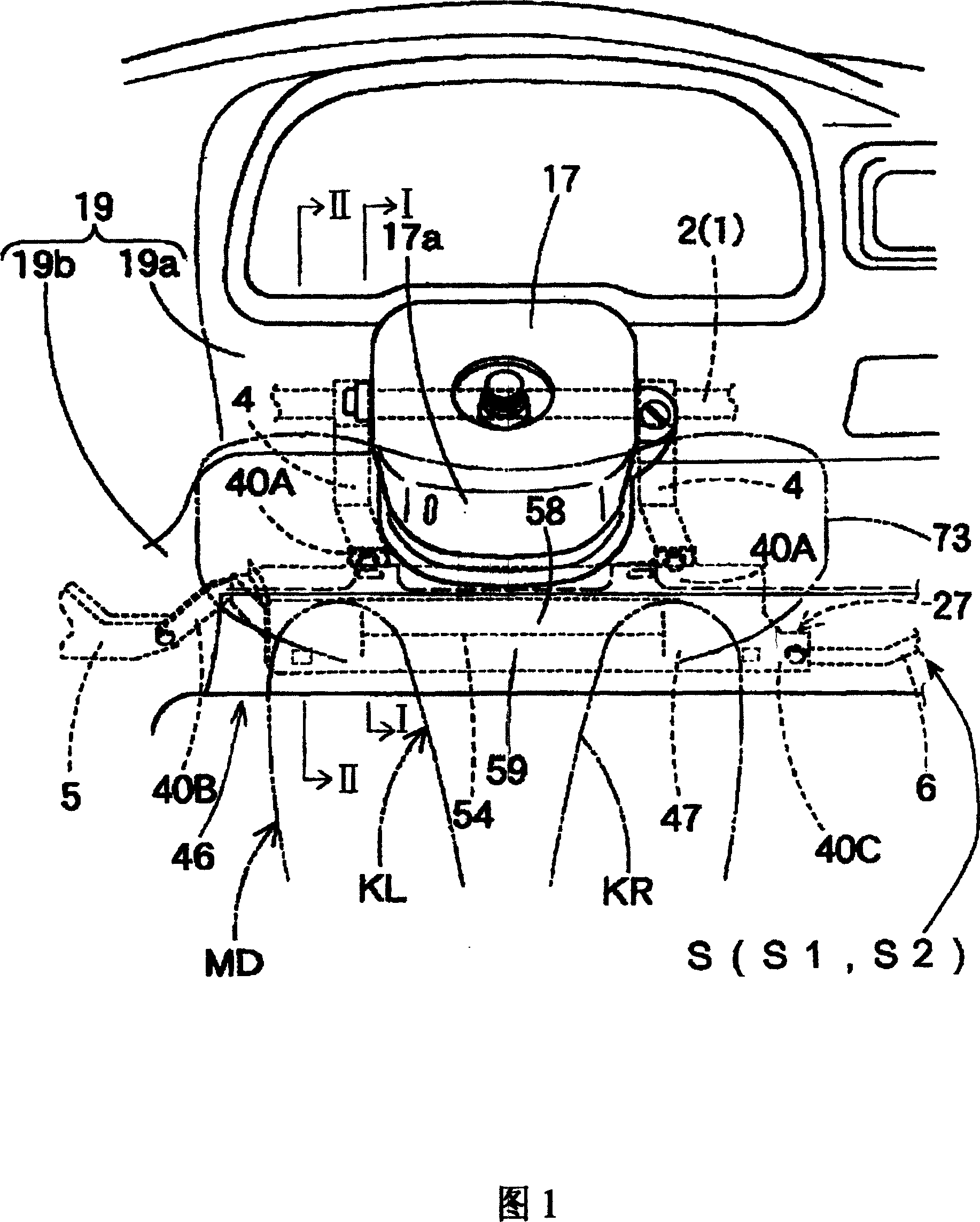
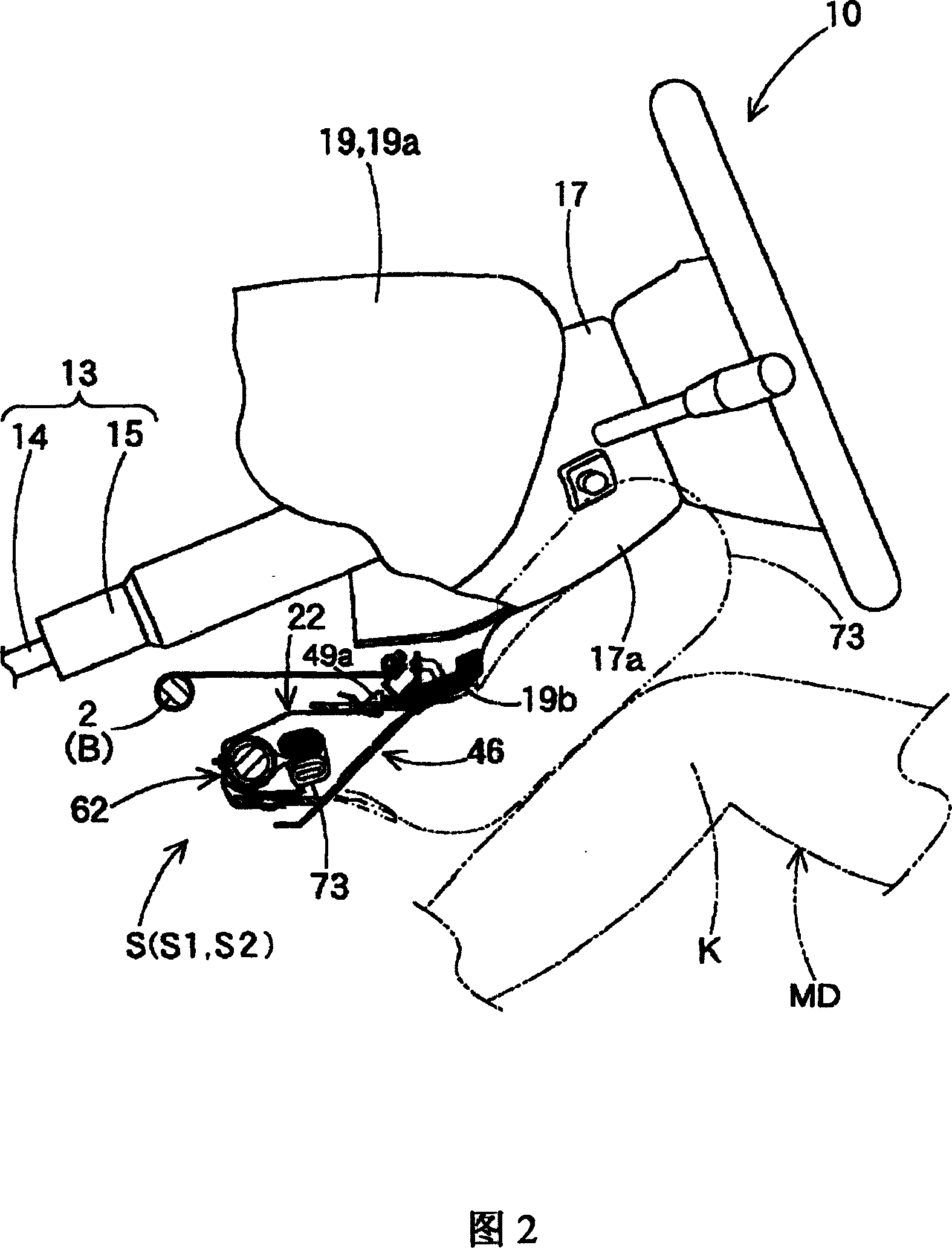
[0056] As shown in FIGS. 1 and 2, the knee protection airbag device S according to the first embodiment of the present invention is arranged below the steering column 13 on the front side of the vehicle of the occupant MD to protect the knees K (KL and KR) of the occupant MD. ).
[0057] Incidentally, terms related to directions mentioned herein, that is, "front and rear", "vertical", and "left and right" used in this specification are in the state where the knee airbag device S is installed in the vehicle. Next, when defining the forward direction of the vehicle as the front side, based on this definition of the front side, the terms "front and rear", "vertical", and "left and right" related to directions are defined.
[0058] As shown in FIG. 2 , the steering column 13 includes: a main shaft 14 connected to the front side of the steering wheel 10 ; and a column tube 15 covering around the main shaft 14 . A tilt mechanism (not shown), a telescopic mechanism (not shown), etc....
no. 2 approach
[0108] Next, a knee protection airbag device S1 according to a second embodiment of the present invention will be described below with reference to FIGS. 1 , 7 to 9 . In the second embodiment, the same parts as those in the first embodiment are denoted by the same reference numerals, and only the parts different from the first embodiment will be described below.
[0109] The knee protection airbag device S1 according to the second embodiment, as shown in FIG. KL, KR).
[0110] In the second embodiment, at the same position in the fitting piece 49 as in the first embodiment, that is, on the rear side of the engagement hole 49a, a protrusion 49f protruding upward and serving as a stopper portion is provided. The protrusion 49f is configured as a thicker portion protruding from a part of the mounting piece 49, and has the same width as the left-right direction of the mounting piece 49 (see FIG. 8).
[0111] As shown in FIGS. 7 and 9 , the protrusion 49f is composed of a first i...
no. 3 approach
[0119] Next, a knee protection airbag device S2 according to a third embodiment of the present invention will be described below with reference to FIGS. 1 and 10 . Incidentally, in the third embodiment, the same parts as those in the first embodiment are denoted by the same reference numerals, and only the parts different from the first embodiment will be described below.
[0120] The knee protection airbag device S2 according to the third embodiment, as shown in FIG. KL, KR).
[0121] In the third embodiment, as shown in FIG. 10 , a stopper portion 35 is formed on the upper surface of the upper fixing portion 32 a on the rear side of the claw-shaped upper locking portion 34 .
[0122] Similar to the storage part 23 and the upper fixing part 32a, the stopper part 35 is made of sheet metal, and the stopper part 35 is fixed to the upper side by a method similar to that used to fix the upper fixing part 32a to the upper peripheral wall part 24a of the storage part 23. The upper...
PUM
 Abstract
Description
Claims
Application Information
 - R&D
- Intellectual Property
- Life Sciences
- Materials
- Tech Scout
- Unparalleled Data Quality
- Higher Quality Content
- 60% Fewer Hallucinations
Browse by: Latest US Patents, China's latest patents, Technical Efficacy Thesaurus, Application Domain, Technology Topic, Popular Technical Reports.
© 2025 PatSnap. All rights reserved.Legal|Privacy policy|Modern Slavery Act Transparency Statement|Sitemap|About US| Contact US: help@patsnap.com