
Oscillating piston engine

一种活塞式发动机、回转运动的技术,应用在旋转活塞式发动机、摆动活塞式发动机、摆动活塞式发动机等方向,能够解决活塞延迟、运行平稳性不利影响、不能到达UT位置等问题,达到运行平稳性改善的效果

Inactive Publication Date: 2007-08-29
赫伯特·许特林
View PDF1 Cites 3 Cited by
  • Summary
  • Abstract
  • Description
  • Claims
  • Application Information

AI Technical Summary

Problems solved by technology

In this regard, there can even be undesirable situations where at least one piston is delayed or does not reach its UT position at all
This has a detrimental effect on the running characteristics of such rotary piston engines, especially the smoothness of running

Method used


Image

  • Oscillating piston engine
  • Oscillating piston engine
  • Oscillating piston engine

Examples


Embodiment Construction

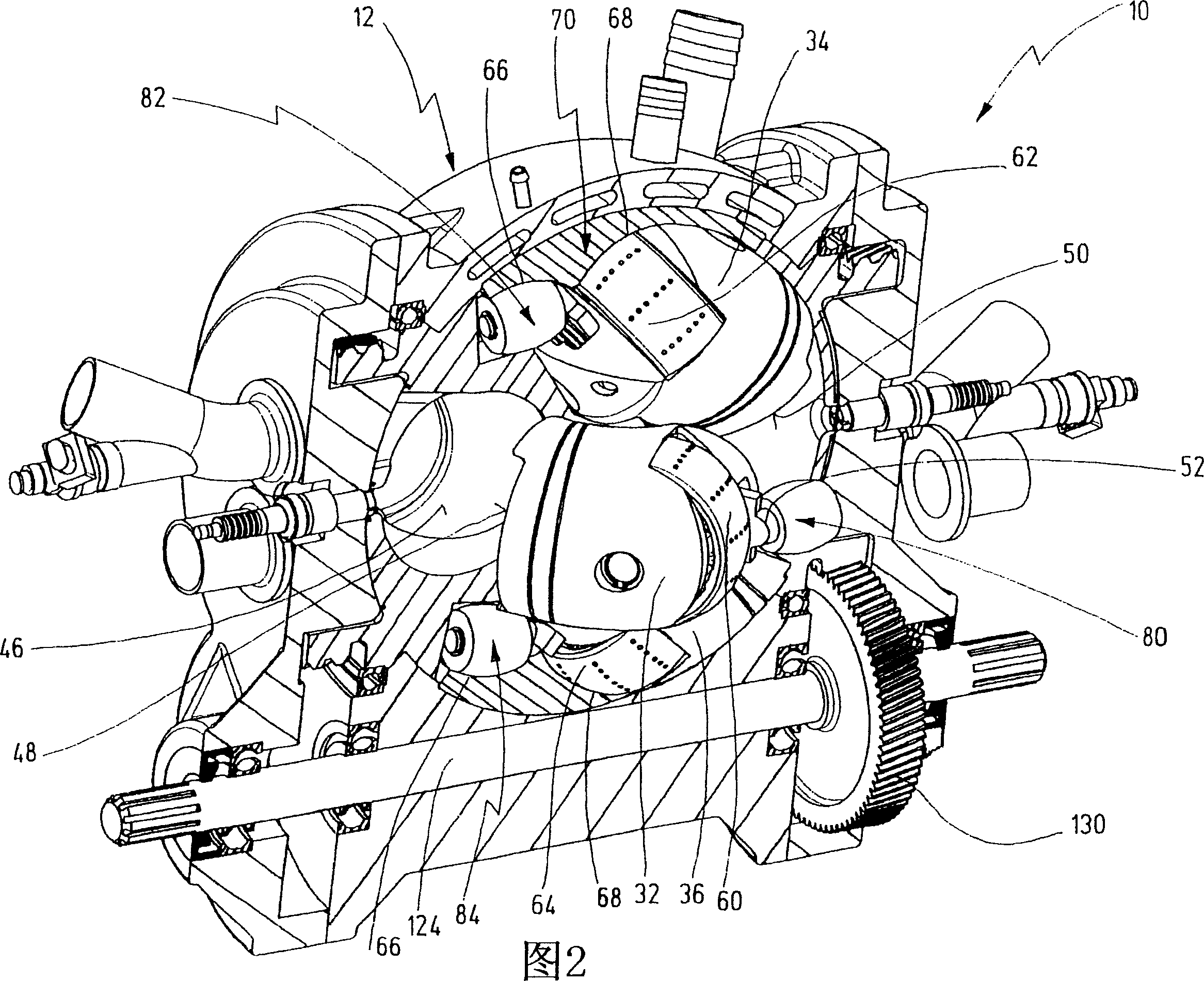
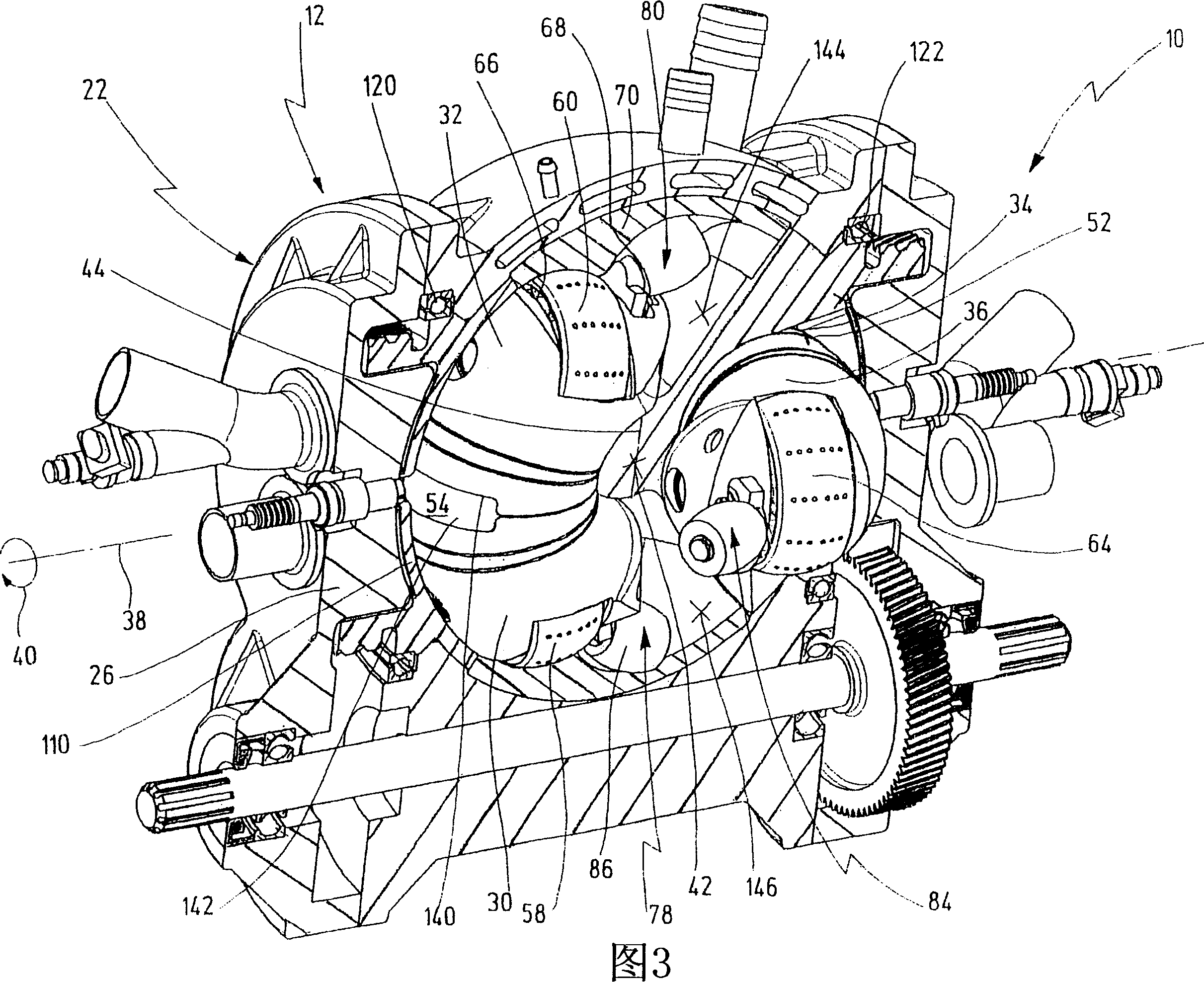
[0042] Figures 1-4 show a rotary piston engine generally indicated at 10 . Additional details of the rotary piston engine 10 are shown in Figures 5-10.

[0043] The rotary piston engine 10 is configured as an internal combustion engine as a whole, but it can also be used as a pump or a compressor after corresponding changes.

[0044] The rotary piston engine 10 has a housing 12 shown closed in FIG. 1 . The housing 12 has a spherical central housing section 14 . The central housing section 14 is composed of two half housings 16 and 18 which are connected to one another via a flange 20 .

[0045] The housing 12 also has a first end face 22 and a second end face 24 opposite the first end face 22 .

[0046] The first end face 22 is formed by an end-face housing cover 26 and the second end face 24 is formed by an end-face housing cover 28 . The housing covers 26 and 28 are connected to the central housing section 14 or its two half housings 16 and 18 . The housing covers 26 an...


PUM


Abstract

The invention relates to an oscillating piston engine comprising a housing (12) wherein at least one piston (30) is arranged. Said piston can revolve about a rotation axis (38) which is fixed in relation to the housing (12), and which, when revolving about the rotation axis (38), performs reciprocating oscillating movements about an oscillating axis (42) running perpendicular to the rotation axis (28), between a first end position (OT) and a second end position (UT). The at least one piston (30) comprises a first running element (58) which extends along at least one control cam (66) when revolving the piston (30) about the rotation axis (38). Said control cam is configured in such a manner that the pivoting movements of the at least one piston (30) are derived from the peripheral movement of the running element (58) along said control cam. Return means for supporting the return of the at least one piston (30) at least from the first end position (OT) into the second end position (UT) are associated with the piston in addition to the running element (58).

Description

technical field [0001] The invention relates to a rotary piston engine having a casing in which at least one piston is arranged, the piston being rotatable in the casing around a fixed axis of rotation of the casing and rotating around the axis of rotation perpendicular to the axis of rotation in a first A reciprocating rotary movement takes place between an end position and a second end position, wherein at least one piston has a first operating mechanism which travels along at least one control curve when the piston rotates around the axis of rotation, the control curve being formed such that at least The rotary motion of a piston is derived from the rotary motion of the running gear along the control curve. Background technique [0002] Such a rotary piston engine is known from document WO 03 / 067033 A1. [0003] The rotary piston engine and in particular the rotary piston engine according to the invention can be used as an internal combustion engine, as a pump or as a co...

Claims


Application Information

Patent Timeline
Patent Type & Authority Applications(China)
IPC IPC(8): F01C3/02F01C9/00F04C9/00
CPCF01C9/005Y02T10/17F01B9/06F01C21/0836F01C21/0872F02B53/04F01C21/089Y02T10/12
Inventor 赫伯特·许特林
Owner 赫伯特·许特林
Learn More