


Quick Research
Generate reliable direction feasibility study reports for your R&D in just a few steps.

Technical Q&A
Discover and master advanced knowledge NOW. Basics, ideas, possibilities, all at once.

Find Solutions
As an expert in R&D theories, this can generate solutions to your technical problems instantly.

Evaluate Feasibility
Analyze your overall solution with one click, know your potential R&D risks in advance.

Monitor Landscape
Get weekly tech updates, stay abreast of the latest tech innovations and key insights.
Lining building machine
A lining machine and vibrating motor technology, applied in irrigation pipelines, applications, construction, etc., can solve problems such as difficult to ensure the compaction effect, and achieve the effects of simple structure, guaranteed lining quality, and high degree of automation
- Summary
- Abstract
- Description
- Claims
- Application Information
AI Technical Summary
Problems solved by technology
Method used
Image


Examples
Embodiment Construction
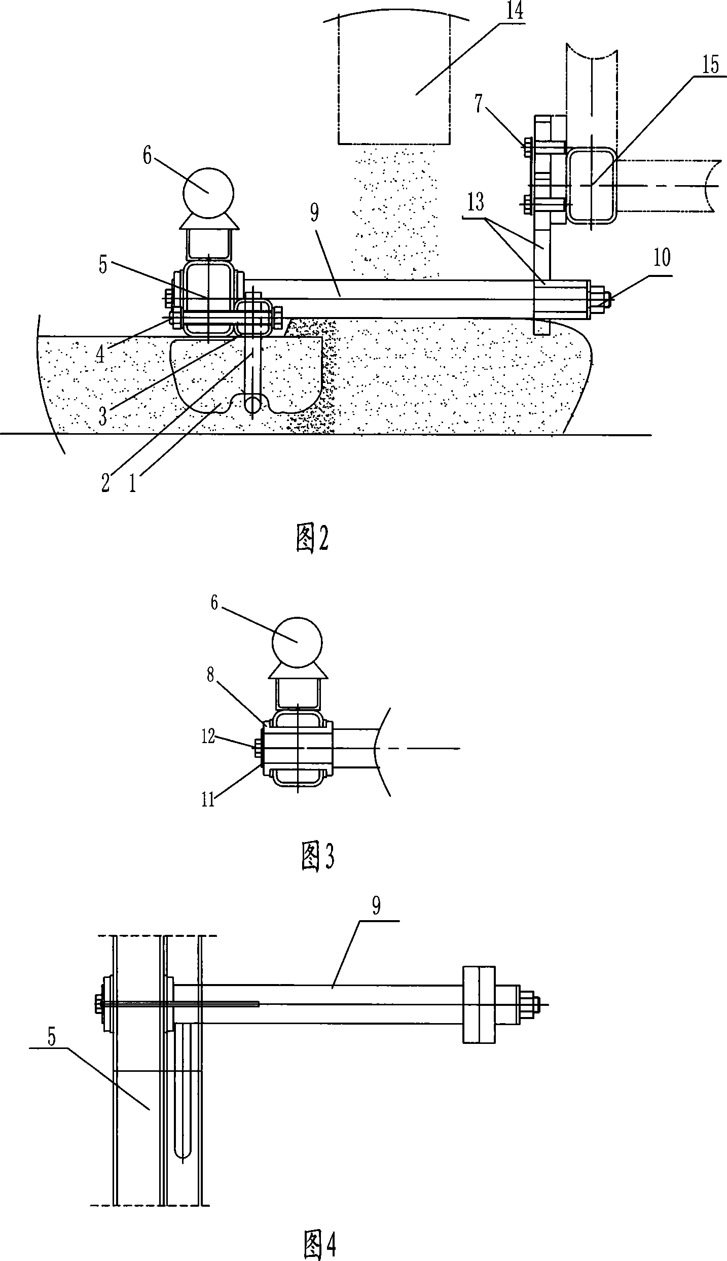
[0014] As shown in the figure, this embodiment includes a main frame 15 and a distribution cart installed on the main frame 15. A vibrating and smoothing mechanism is arranged below the discharge port 14 of the distribution cart. This embodiment is installed along the length of the main frame 15. There are 12 groups of vibrating and smoothing mechanisms. The mechanism is mounted on the main frame 15 via an adjustable support plate 13 . One end of the support rod 9 is installed on the adjustable support plate 13 , and the adjustment of the distance between the end and the main frame 15 is realized by the adjustable support plate 13 or its connection with the adjustable support plate 13 . Its structure can adopt the prior art. The other end of the support rod 9 is connected with the vibrating beam 5 through the shock absorber 8 . The vibrating beam 5 is strip-shaped, and it is perpendicular to the moving direction of the equipment, and plays a smoothing effect during equipment...
PUM
 Abstract
Description
Claims
Application Information
 - R&D Engineer
- R&D Manager
- IP Professional
- Industry Leading Data Capabilities
- Powerful AI technology
- Patent DNA Extraction
Browse by: Latest US Patents, China's latest patents, Technical Efficacy Thesaurus, Application Domain, Technology Topic, Popular Technical Reports.
© 2024 PatSnap. All rights reserved.Legal|Privacy policy|Modern Slavery Act Transparency Statement|Sitemap|About US| Contact US: help@patsnap.com