Double-driving foot sandwich converter type longitudinal and bending linear ultrasonic motor
A technology of linear ultrasonic motors and transducers, applied in the direction of generators/motors, piezoelectric effect/electrostrictive or magnetostrictive motors, electrical components, etc., can solve the problems of inability to form product serialization, low motor efficiency, Noise and other problems, to achieve the effect of low noise, reduced loss and high efficiency
- Summary
- Abstract
- Description
- Claims
- Application Information
AI Technical Summary
Problems solved by technology
Method used
Image
Examples
specific Embodiment approach 1
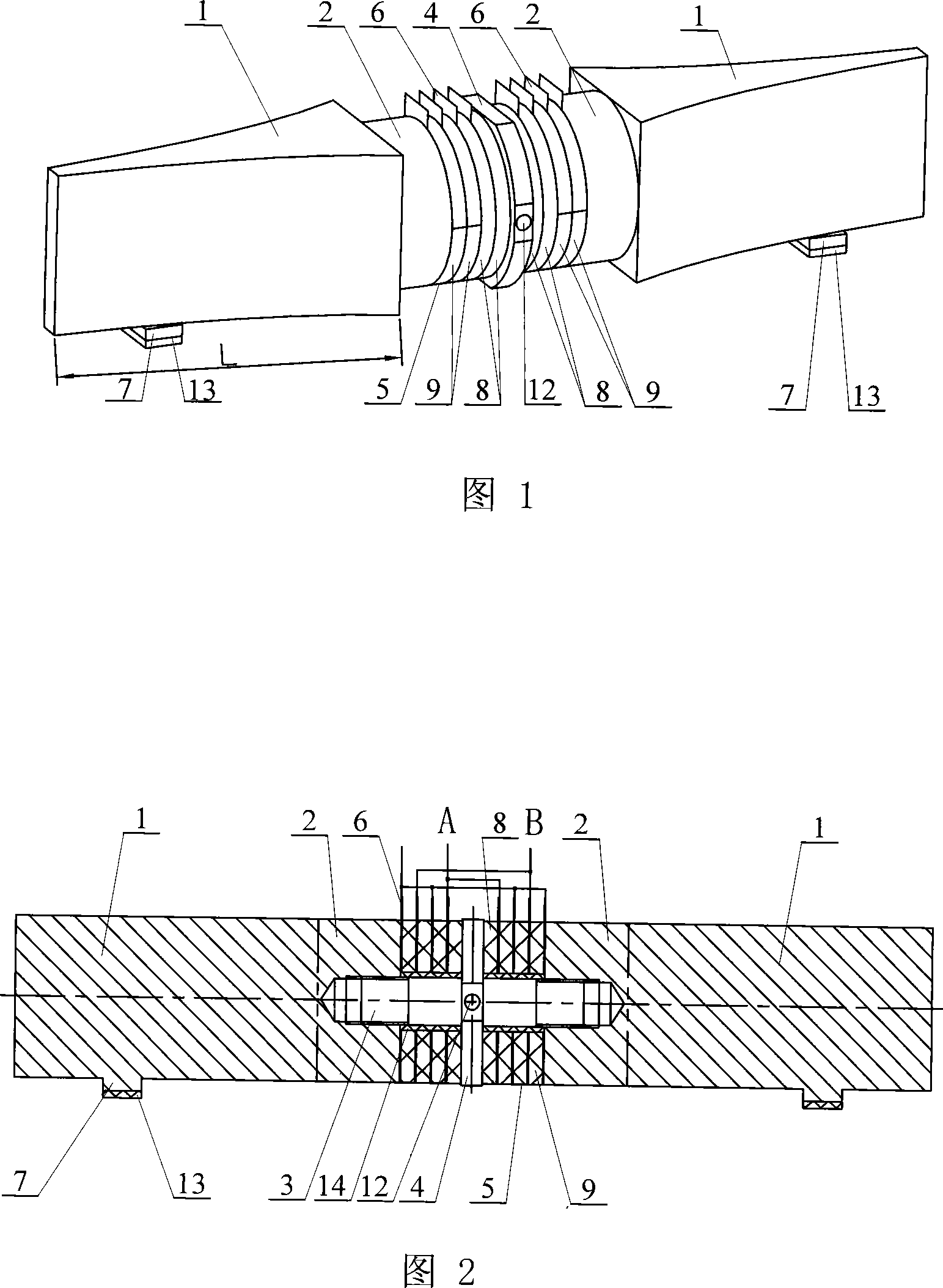
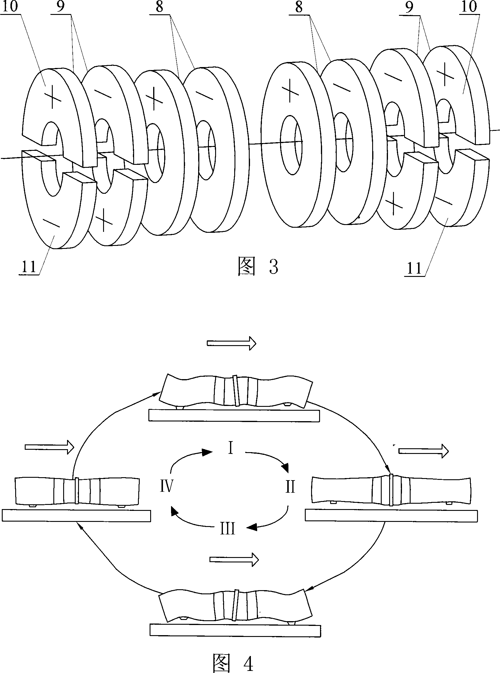
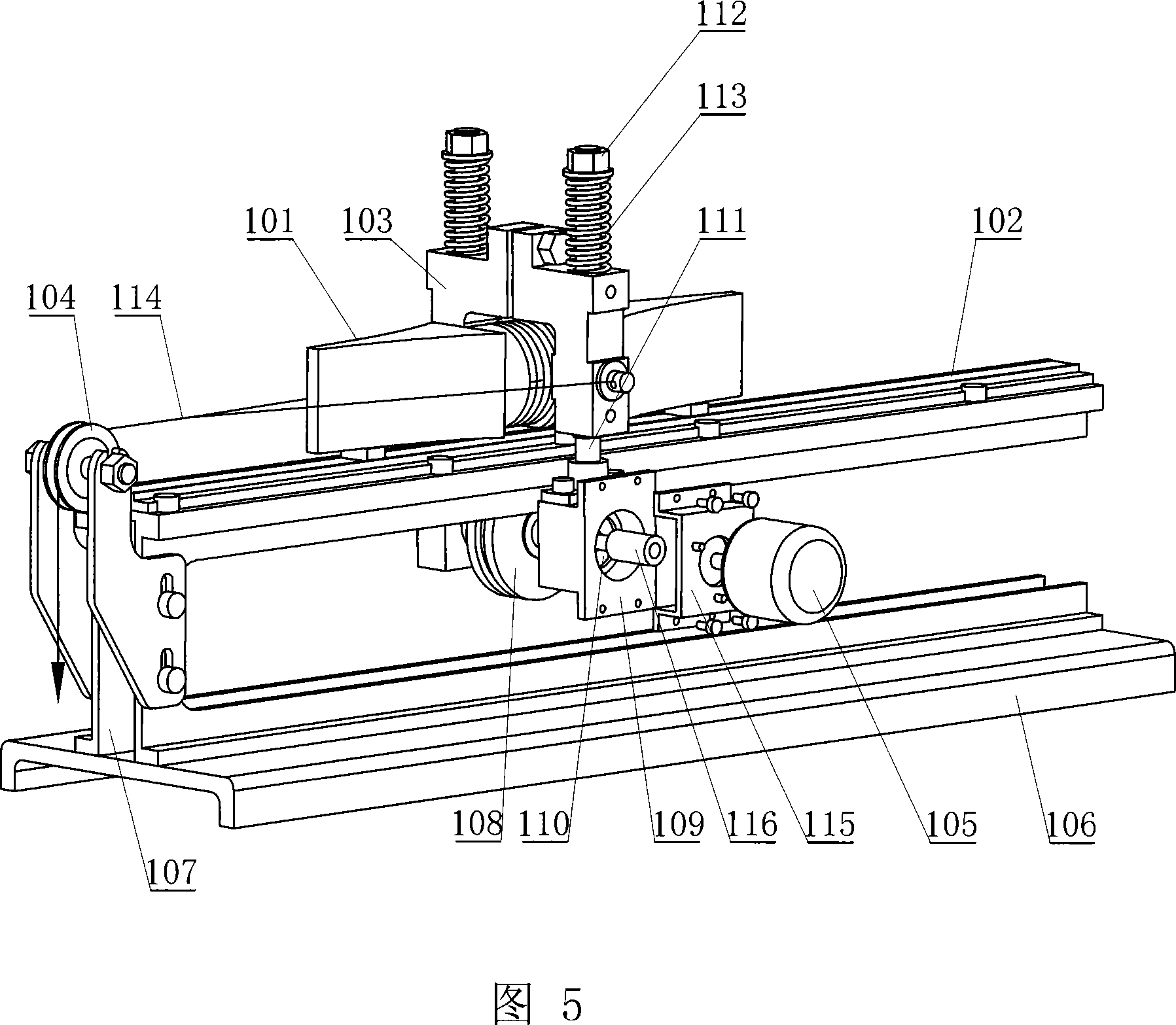
[0007] Specific embodiment 1: This embodiment is described in conjunction with Fig. 1 to Fig. 3. This embodiment is composed of a sandwich transducer and a driving foot 7; , flange 4, piezoelectric ceramic sheet group 5, and thin copper sheet 6; the middle position on the stud 3 is provided with a flange 4 made integral with the stud 3, and the stud 3 on the left side of the flange 4 The upper and the studs 3 on the right side of the flange 4 are equipped with piezoelectric ceramic sheet groups 5 respectively, between the piezoelectric ceramic sheets of the piezoelectric ceramic sheet group 5 and between the piezoelectric ceramic sheet group 5 and the end cover 2 respectively. The thin copper sheet 6 is installed as an electrode, the piezoelectric ceramic sheet group 5 and the thin copper sheet 6 are fastened together with the end cover 2 through the stud 3, and the end cover 2 is fixedly connected with the large end of the frequency modulation horn 1, so The piezoelectric cer...
specific Embodiment approach 2
[0009] Specific embodiment two: this embodiment is described in conjunction with Fig. 1 and Fig. 2, two small conical holes 12 are drilled at the joints of the longitudinal bending vibration nodes of the outer cylindrical surface of the flange 4 of the present embodiment, as the pre-tightening force of the linear ultrasonic motor The gripping point of a mechanism used to apply preload to generate drive friction. Choose to drill two small conical holes 12 at this position to prevent resonance frequency drift and vibration distortion and reduce energy loss. Other components and connections are the same as those in the first embodiment.
specific Embodiment approach 3
[0010] Specific embodiment three: This embodiment is described in conjunction with Fig. 1 and Fig. 2. The difference between this embodiment and specific embodiment one is: this embodiment also adds a hard ceramic friction plate 13; the hard ceramic friction plate 13 Bond with the lower end surface of the driving foot 7. Such setting can prevent the driving foot 7 from wearing out and prolong the service life of the driving foot 7 .
PUM
 Abstract
Description
Claims
Application Information
 - R&D
- Intellectual Property
- Life Sciences
- Materials
- Tech Scout
- Unparalleled Data Quality
- Higher Quality Content
- 60% Fewer Hallucinations
Browse by: Latest US Patents, China's latest patents, Technical Efficacy Thesaurus, Application Domain, Technology Topic, Popular Technical Reports.
© 2025 PatSnap. All rights reserved.Legal|Privacy policy|Modern Slavery Act Transparency Statement|Sitemap|About US| Contact US: help@patsnap.com


