
Circuit base board, its encapsulation structure, and making method of the encapsulation structure

A circuit substrate and circuit board technology, applied in the directions of printed circuit manufacturing, printed circuits, printed circuit components, etc., can solve the problems of increasing the cost of the process, increasing the complexity of the process, and achieve the effect of reducing the cost of the process and simplifying the process.

Inactive Publication Date: 2010-06-09
IND TECH RES INST
View PDF4 Cites 0 Cited by
  • Summary
  • Abstract
  • Description
  • Claims
  • Application Information

AI Technical Summary

Problems solved by technology

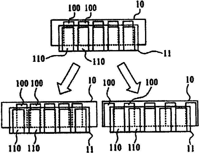
[0015] Another object of the present invention is to provide a circuit board and its assembly structure and the manufacturing method of the assembly structure, avoiding the thermal deformation of the circuit board in the prior art, it is necessary to make a circuit board with different electrode spacings and combine it with the circuit board This leads to problems such as increasing the complexity of the process and relatively increasing the cost of the process

Method used


Image

  • Circuit base board, its encapsulation structure, and making method of the encapsulation structure
  • Circuit base board, its encapsulation structure, and making method of the encapsulation structure
  • Circuit base board, its encapsulation structure, and making method of the encapsulation structure

Examples


Embodiment 1

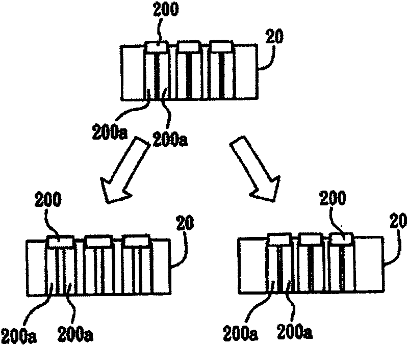
[0030] see Figure 2A It is a schematic plan view of the circuit substrate of the present invention. A plurality of electrodes 200 are formed on the surface of the circuit substrate 20, and each electrode 200 is formed with at least two forked structures 200a. As shown in the figure, the circuit substrate 20 expands the electrode 200 used for signal conduction with the outside world and splits it into two forks, that is, a distance is formed between the at least two forked structures 200a to increase the The combination probability that the electrode can be aligned with the external circuit board electrode.

[0031]The circuit substrate 20 is a plastic substrate, such as a flexible substrate (flexible substrate) used in a flexible display, and the insulating plastic substrate used in the circuit substrate 20 is, for example, polyethersulfone (Polyethersulfone, PES), and its glass The conversion temperature is about 200-220°C, and the thermal expansion coefficient is about 50-...

Embodiment 2

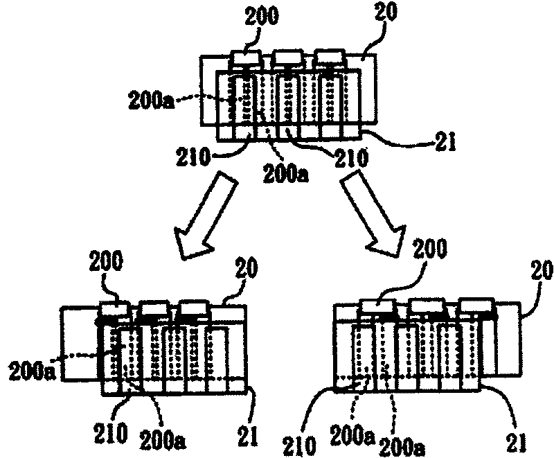
[0043] Figure 4A and Figure 4B It is a schematic plan view of Embodiment 2 of the circuit substrate of the present invention, and a schematic plan view of Embodiment 2 of the structure of the circuit substrate.

[0044] As shown in the figure, the circuit substrate and its assembly structure of Embodiment 2 of the present invention are substantially the same as the above-mentioned Embodiment 1, the main difference is that the forked structure formed on the circuit substrate 30 on the electrode 300 is in the shape of a grid 300a, so , not only can further increase the probability of alignment combination between the electrode 300 of the circuit substrate 30 and the electrode 310 of the external circuit board 31, but also increase the number of conductive particles captured in the anisotropic conductive film under the electrode of the circuit substrate 30 and the circuit board 31, and reduce the Combine resistors and increase the chance of conduction.

[0045] Furthermore, i...


PUM


Abstract

The disclosed circuit substrate includes multiple electrodes on surface to form bifurcation. The corresponding manufacture method for this substrate comprises: providing a circuit substrate with multiple electrodes and bifurcation, and a circuit board with multiple electrodes; combining these electrodes on board to the bifurcation on substrate, and cutting the superposition of bifurcation on substrate combined with different electrode. This invention can increase combination probability with external electrode when expending or shrinking, and avoids short circuit.

Description

technical field [0001] The present invention relates to a circuit substrate and its construction structure and a method for manufacturing the construction structure, in particular to a flexible substrate and its construction structure applicable to a display, and the flexible substrate construction structure method of making. Background technique [0002] Due to the advancement of technology, Flat Panel Display (FPD) has become an important electronic product at present. Almost all kinds of electrical appliances in life can be applied to this flat panel display, such as TV, outdoor billboards, display screens of electronic instruments and Electronic watches, etc., so the optoelectronic industry has made every effort to develop and improve in this field. From the early cathode ray tube (Cathode Ray Tube, CRT) to the current popular liquid crystal display (Liquid Crystal Display, LCD), various flat-panel displays have been continuously are being improved and updated. Further...

Claims


Application Information

Patent Timeline
Patent Type & Authority Patents(China)
IPC IPC(8): H05K1/02H05K3/00
Inventor 林耀生陈泰宏
Owner IND TECH RES INST
Learn More