


Quick Research
Generate reliable direction feasibility study reports for your R&D in just a few steps.

Technical Q&A
Discover and master advanced knowledge NOW. Basics, ideas, possibilities, all at once.

Find Solutions
As an expert in R&D theories, this can generate solutions to your technical problems instantly.

Evaluate Feasibility
Analyze your overall solution with one click, know your potential R&D risks in advance.

Monitor Landscape
Get weekly tech updates, stay abreast of the latest tech innovations and key insights.
Optical access network system
A technology of network system and optical terminal, which is applied in the field of optical access network system, and can solve problems such as difficult to obtain A/D converter and digital multiplier
- Summary
- Abstract
- Description
- Claims
- Application Information
AI Technical Summary
Problems solved by technology
Method used
Image

Examples
no. 1 example
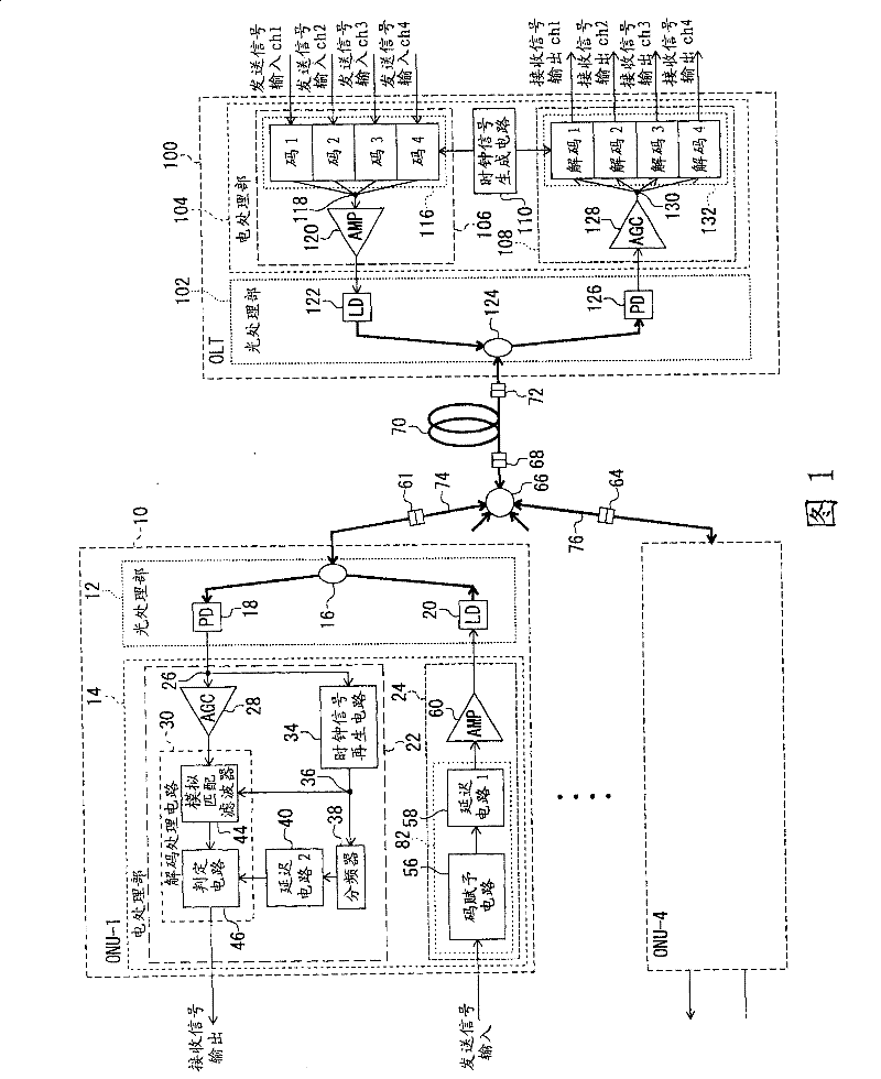
[0037] refer to figure 1 The configuration and operation of the optical access network system of the first embodiment will be described. figure 1 is a schematic block configuration diagram showing the optical access network system of the first embodiment. figure 1 The optical access network system shown assumes that the number of subscribers (number of users) is 4, that is, there are 4 optical terminal devices. However, although there are 4, the following description holds regardless of the number. exist figure 1 In , in order to identify a plurality of optical terminal devices, the optical terminal device to which the first channel is allocated is represented as ONU-1, and the optical terminal device to which the fourth channel is allocated is represented as ONU-4. All of ONU-1 to ONU-4 have the same structure. In the subsequent description of the optical access network system of the first embodiment, when describing the configuration of an optical terminal device, it will...
no. 2 example
[0143] refer to Figure 8 The structure and operation of the optical access network system of the second embodiment will be described. Figure 8 is a schematic block diagram of the optical access network system of the second embodiment. In the second embodiment, a case where the number of subscribers is 16 is assumed. The difference from the optical access network system of the first embodiment is that in the optical access network system of the first embodiment, only one signal wavelength is used for communication, while in the optical access network system of the second embodiment In the network system, there is a so-called WDM (Wavelength Division Multiplex) system using four wavelengths as signal wavelengths.
[0144] Thus, relative to the signal wavelength λ 1 The structure of the communicating part is the same as that of the optical access network system of the first embodiment. The wavelength used as the wavelength of the signal uses λ 1 to lambda 4 There are four...
PUM
 Abstract
Description
Claims
Application Information
 - R&D Engineer
- R&D Manager
- IP Professional
- Industry Leading Data Capabilities
- Powerful AI technology
- Patent DNA Extraction
Browse by: Latest US Patents, China's latest patents, Technical Efficacy Thesaurus, Application Domain, Technology Topic, Popular Technical Reports.
© 2024 PatSnap. All rights reserved.Legal|Privacy policy|Modern Slavery Act Transparency Statement|Sitemap|About US| Contact US: help@patsnap.com