
Method and system for communication between IP devices

A device and IP address technology, applied in the field of network communication, can solve the problems of long interruption time and the inability of the Master router to receive internal router information quickly, so as to achieve the effect of short interruption time.

Active Publication Date: 2007-07-25
HUAWEI TECH CO LTD
View PDF0 Cites 28 Cited by
  • Summary
  • Abstract
  • Description
  • Claims
  • Application Information

AI Technical Summary

Problems solved by technology

[0017] During the above-mentioned master router switchover and internal router dynamic routing protocol switchover, the following problems will occur: when router A fails, according to the VRRP mechanism, the occurrence of the failure can be detected relatively quickly, and the router will be reset in a short period of time. B switches to Master router
When the master router is switched over, the switched master router cannot quickly receive the information sent by the internal router
Therefore, using the technical solution provided by the prior art, when the Master router is switched over, the information sent by the internal router to the external network is interrupted for a long time

Method used


Image

  • Method and system for communication between IP devices
  • Method and system for communication between IP devices
  • Method and system for communication between IP devices

Examples


Embodiment Construction

[0039] In order to make the object, technical solution and advantages of the present invention clearer, the present invention will be further described in detail below in conjunction with the accompanying drawings.

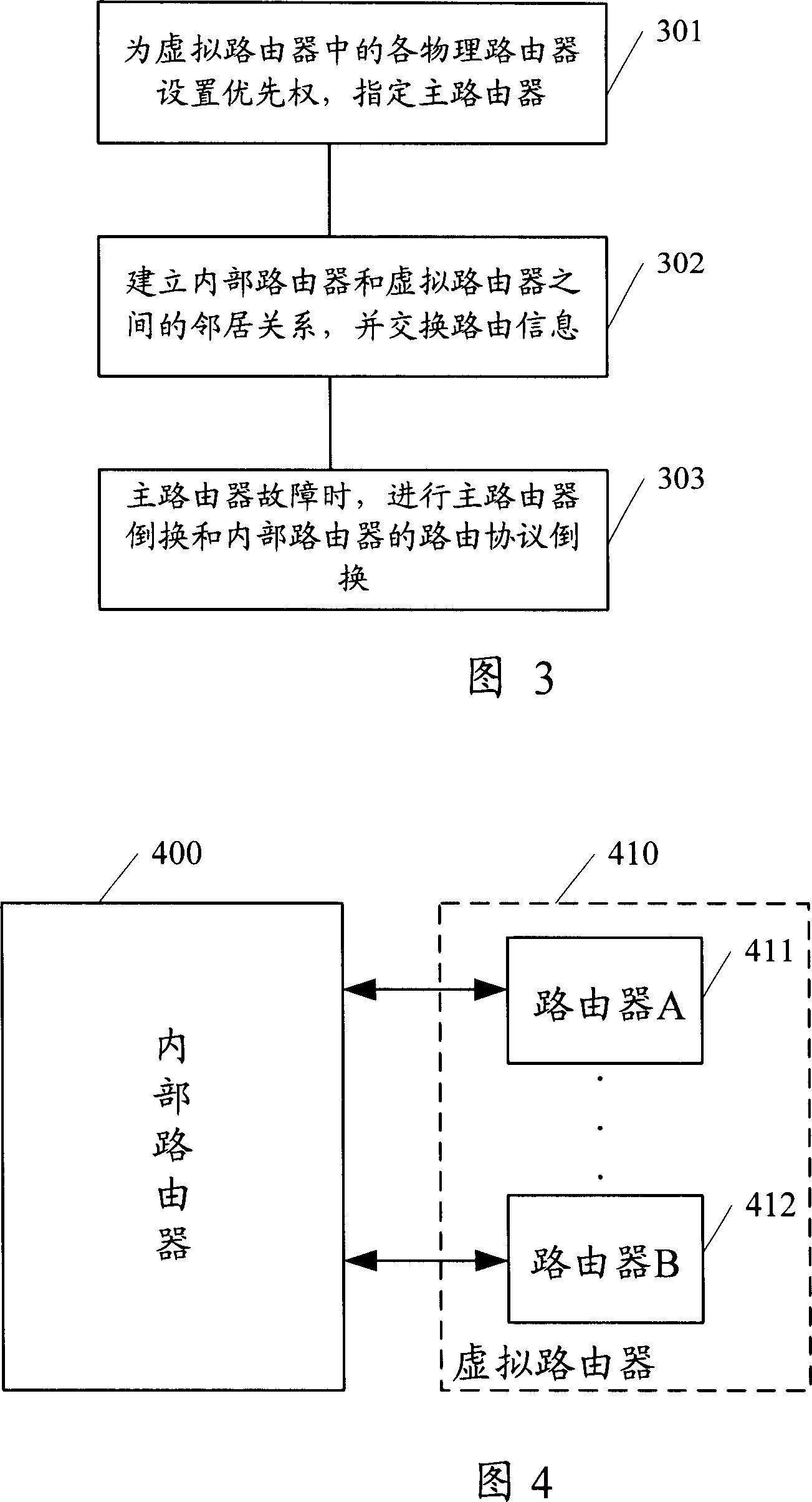
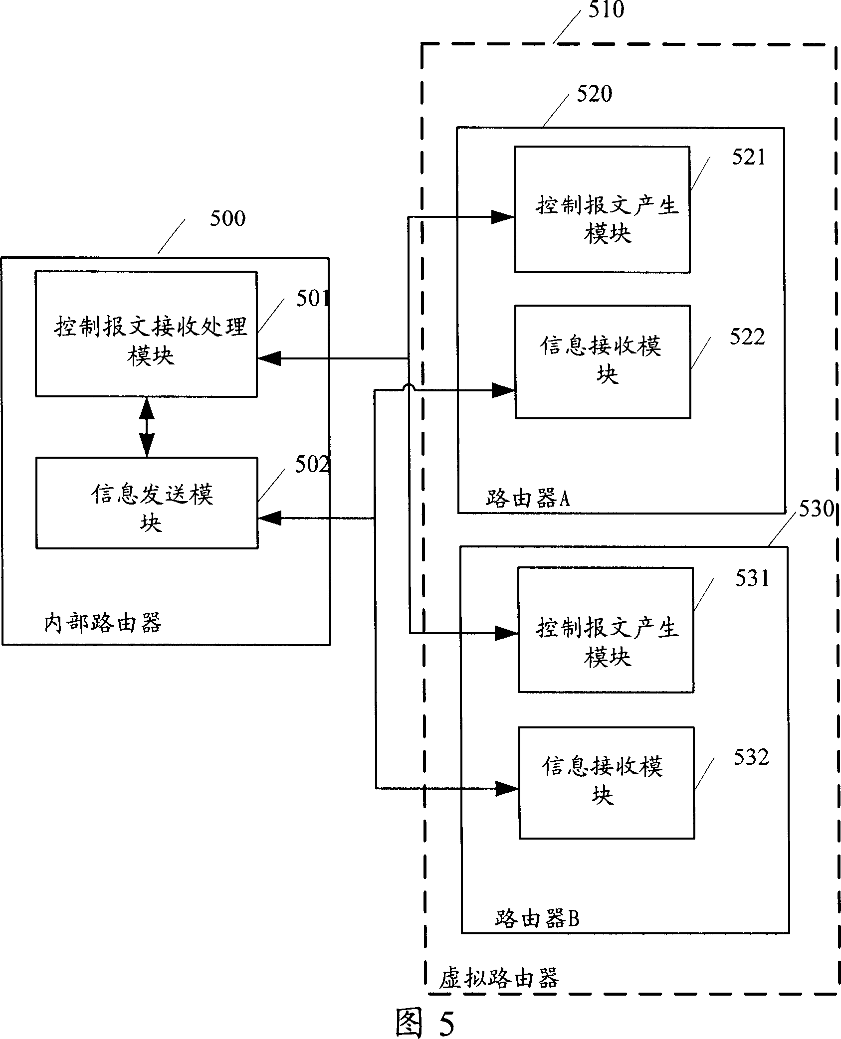
[0040] An embodiment of the present invention includes: the internal router obtains the virtual IP address of the virtual router, uses the obtained virtual IP address as a destination address, sends information to the virtual router, and sends the information to the master router. When the master router is switched, the conversion of the internal router to the dynamic routing protocol is consistent with the switching of the virtual router to the master router, and the internal router sends information to the switched virtual router according to the virtual IP address. When the switchover of the master router occurs, the solution provided by the invention can ensure that the master router in the virtual router can continuously receive the information sent by the int...


PUM


Abstract

The method comprises: the internal router gets the virtual IP address of the virtual router, takes the virtual address as the destination address, and sends the information about external network to the virtual router. The invention also provide a system used in communication between IP devices. By the provided solution, when Master router swap happens, the conversion of internal dynamic protocol is accordance with the swap between the virtual router and master router so as to ensure the swapped master router is capable to receive the message from internal router in short time.

Description

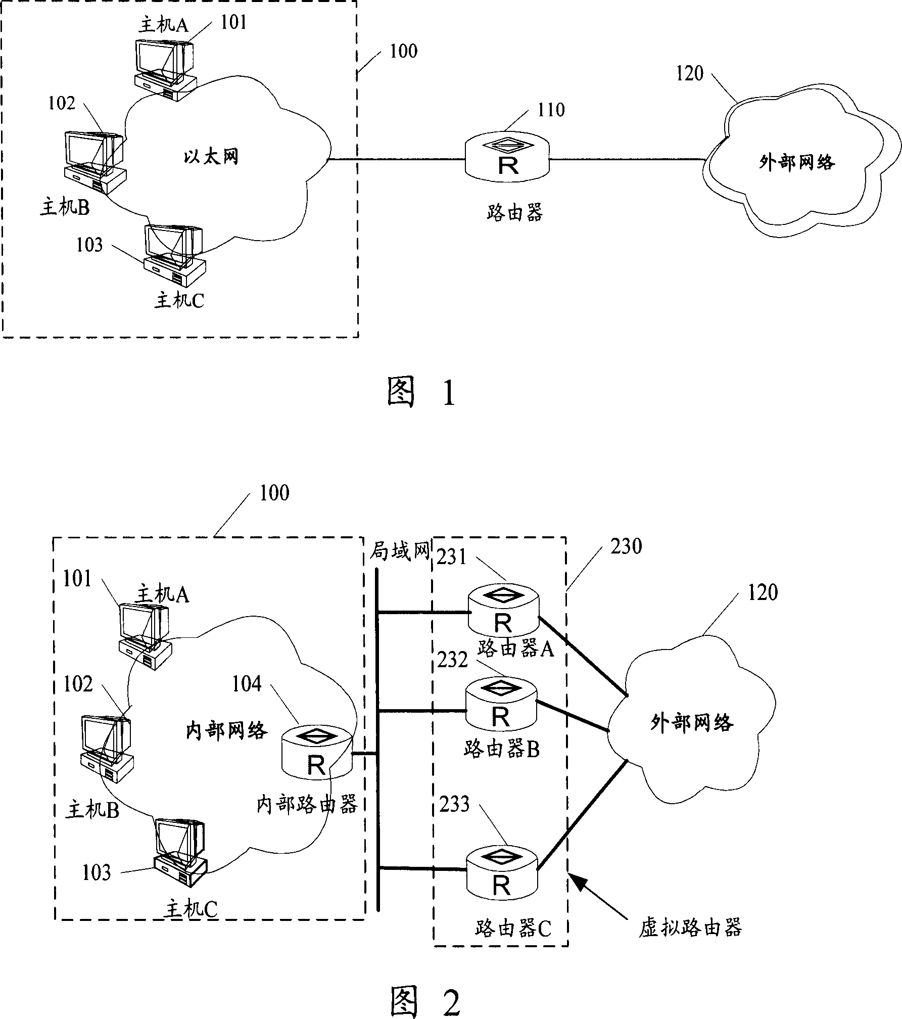
technical field [0001] The invention relates to network communication technology, in particular to a method and system for communicating between IP devices. Background technique [0002] A LAN needs to communicate with an external network through a router. FIG. 1 is a schematic structural diagram of a system in the prior art that enables a LAN to communicate with an external network through a default router. As shown in Figure 1, [0003] The system includes: an Ethernet (Ethernet) 100 , a router 110 and an external network 120 . Among them, host A101, host B102 and host C103 are devices in Ethernet100. The host A101, the host B102, and the host C103 communicate with the external network 120 through the router 110 respectively. [0004] In the schematic diagram of the system structure shown in FIG. 1 , all hosts in the Ethernet 100 exchange information with the external network 120 through the default router 110 . The advantage of this network structure is that it simpli...

Claims


Application Information

Patent Timeline
Patent Type & Authority Applications(China)
IPC IPC(8): H04L12/56H04L29/06H04L29/12H04L12/28H04L12/46H04L45/28H04L45/02H04L45/586
CPCH04L49/70H04L45/28H04L45/60H04L45/02H04L45/586H04L45/03
Inventor 闫刚盛成
Owner HUAWEI TECH CO LTD
Learn More