
Cutting device for sugar cane harvester

A technology of cutting mechanism and harvester, which is applied in the direction of harvester, agricultural machinery and implements, etc. It can solve the problem of increased rate of broken heads, falling in front of the harvester, or falling on the cutter head and blade at a certain angle Problems such as improving and reducing the sugar yield, to achieve the effect of prolonging the service life, reducing the broken head rate, and ensuring the sugar yield

Inactive Publication Date: 2010-01-27
卢志乐
View PDF9 Cites 0 Cited by
  • Summary
  • Abstract
  • Description
  • Claims
  • Application Information

AI Technical Summary

Problems solved by technology

Although the cutting mechanism for sugarcane has increased blade cutting performance and improved cutting efficiency; but because there is no special mechanism to send the cut and fallen sugarcane to the follow-up process in time, the sugarcane cannot be completely cut in the desired direction and direction. In the subsequent process of being transported in a timely and smooth manner, some of them will fall in front of the harvester, or fall on the cutter head and blade at a certain angle, and turn around before entering the subsequent process. The blade will soon make another cut on the cane stalk, causing the cut sugarcane to suffer two or more cuts, greatly increasing the rate of head breakage and reducing the sugar yield

Method used


Image

  • Cutting device for sugar cane harvester
  • Cutting device for sugar cane harvester
  • Cutting device for sugar cane harvester

Examples


Embodiment Construction

[0023] The present invention will be further described in detail below in conjunction with the accompanying drawings and embodiments.

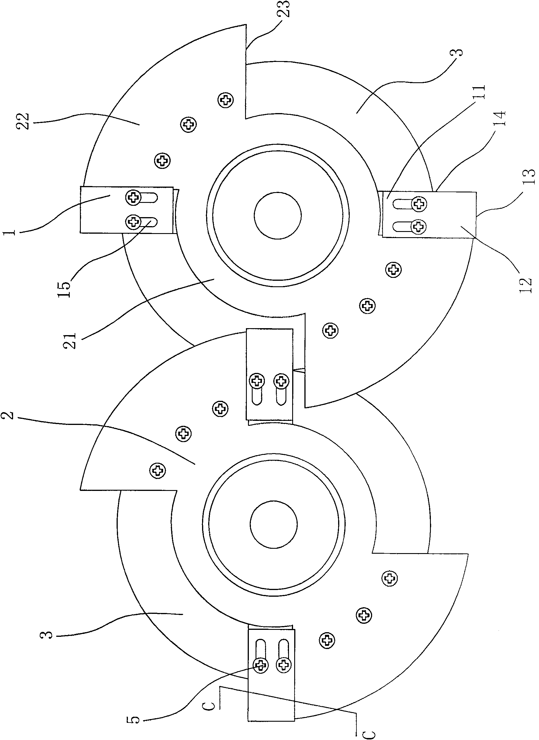
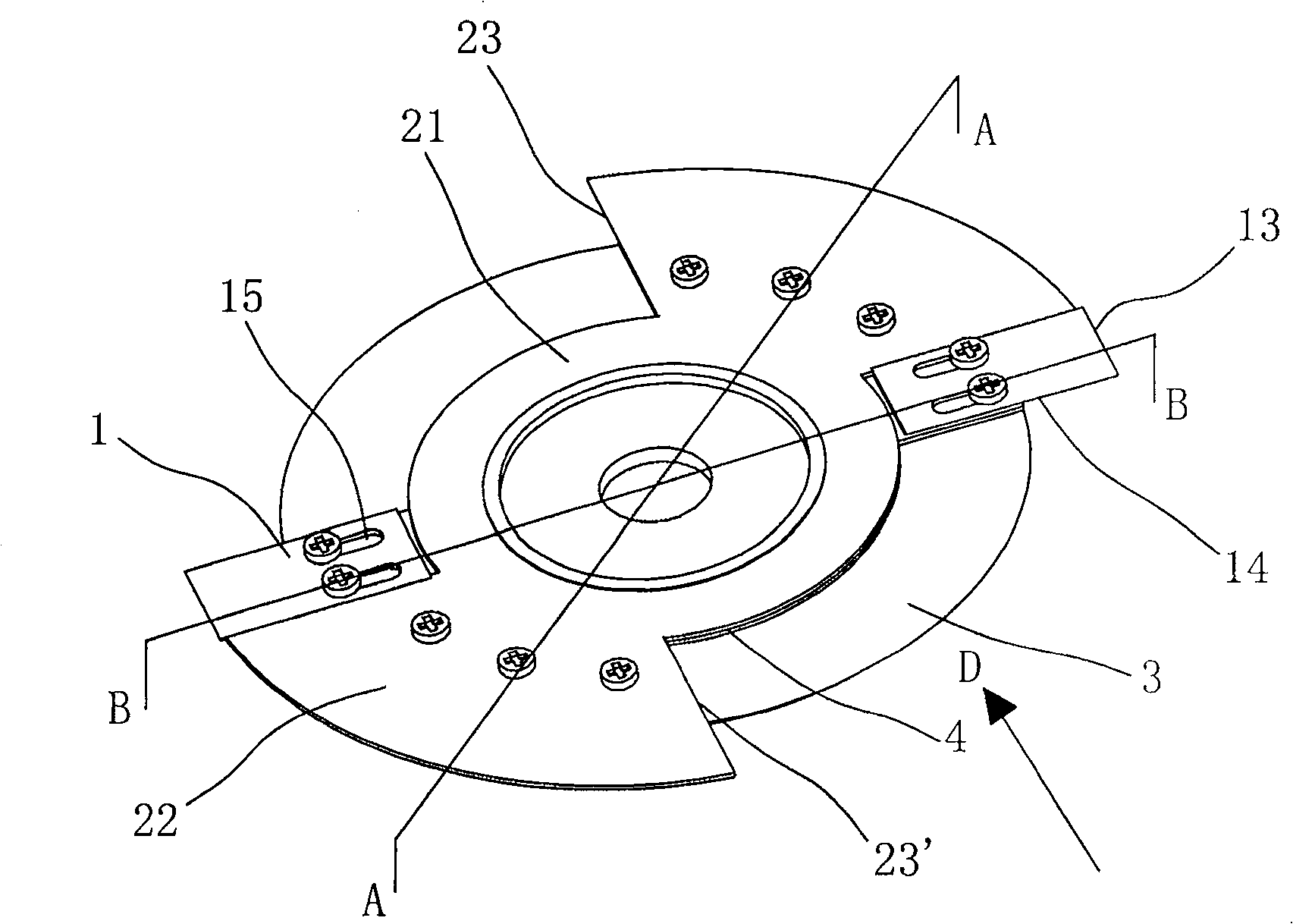
[0024] as 1 to Figure 7 As shown, the cutting mechanism of the sugarcane harvester includes left and right cutterheads 3, blades 1, supporting plates 2 and backing plates 4 with the same structure.

[0025] in,

[0026] The cutter head 3 is driven by an external force, for example, a rotating shaft (not shown) driven by an intermeshing gear set (not shown) connected to a motor shaft (not shown) To drive, the rotating shaft is fixed on the rotating hole 31 provided at the center of the cutter head.

[0027] The backing plate 4 is fixed below the cutterhead 3. In this embodiment, the middle part of the backing plate 4 is a circular ring concentric with the cutterhead 3, and the outside of the backing plate 4 is a sector extending outward from the circular ring. And the outer end edge of backing plate 4 coincides with the outer end edge of cu...


PUM


Abstract

The invention relates to a cutting mechanism used for a cane harvester, which comprises two cutter heads which can be rotated oppositely, wherein one to three blade(s) is (are) fixed on each cutter head, and a backing plate is arranged between the cutter heads and the blade(s). The cutting mechanism is characterized in that approximately fan-shaped holding and connecting plates are matched with all the blades, and are fixed on the cutter heads, and the front sides of the holding and connecting plates are tightly propped against the rear sides of the blades; the cutter heads respectively extend out of the exteriors of the holding and connecting plates and the exteriors of the blades, and the thicknesses of the exteriors of the holding and connecting plates are less than or equal to the thicknesses of the exteriors of the blades; and the blades on the two cutter heads are distributed with the matched holding and connecting plates in a mutually staggered manner. Through the arrangement of the holding and connecting plates matched with the blades, the canes lean over the holding and connecting plates after being chopped off, the cane stalks can be smoothly transmitted to the subsequent working procedure in time via the holding and connecting plates, the phenomenon that the canes cannot be cut by the subsequent blades brought along with rotation once and even more times because of the incorrect falling position of the canes does not occur, the broken root rate is greatly reduced, and the sugar generation rate for post-processing of the canes is strongly guaranteed.

Description

technical field [0001] The invention relates to a sugarcane harvester, in particular to a cutting mechanism for a sugarcane harvester. Background technique [0002] Today, with the increasing popularity of mechanical automation, sugarcane farmers have basically got rid of the labor of manually harvesting sugarcane, and use sugarcane harvesters with high efficiency and low labor intensity to harvest sugarcane. The harvesting methods of sugarcane harvesters include cut-off harvesting and whole-stalk harvesting. The current mainstream harvesting method is whole-stalk harvesting, that is, the sugarcane is first pushed down and tilted at a certain angle, and then the cutting mechanism on the sugarcane harvester cuts the sugarcane. In order to ensure that the sugar content of the sugarcane will not be lost after harvesting, it is required that the cut stubble should be 2 to 3 centimeters below the ground, and there should be no damage to the cracks; The leaves and tips of the sug...

Claims


Application Information

Patent Timeline
Patent Type & Authority Patents(China)
IPC IPC(8): A01D45/10
Inventor 卢志乐
Owner 卢志乐
Learn More