
Main circuit of IGBT full bridge inverse conversion power

A full-bridge inverter and main circuit technology, applied in electrical components, output power conversion devices, AC power input conversion to DC power output, etc., can solve damage, IGBT prone to false triggering, IGBT inverter power supply circuit complexity, etc. problem, to achieve the effect of improving reliability

Inactive Publication Date: 2009-12-30
袁忠杰
View PDF6 Cites 1 Cited by
  • Summary
  • Abstract
  • Description
  • Claims
  • Application Information

AI Technical Summary

Problems solved by technology

However, the IGBT inverter power supply circuit is complex, and if the parameter design of each component is unreasonable, it will cause the IGBT to be easily triggered by mistake and be damaged.

Method used


Image

  • Main circuit of IGBT full bridge inverse conversion power
  • Main circuit of IGBT full bridge inverse conversion power
  • Main circuit of IGBT full bridge inverse conversion power

Examples


example 1

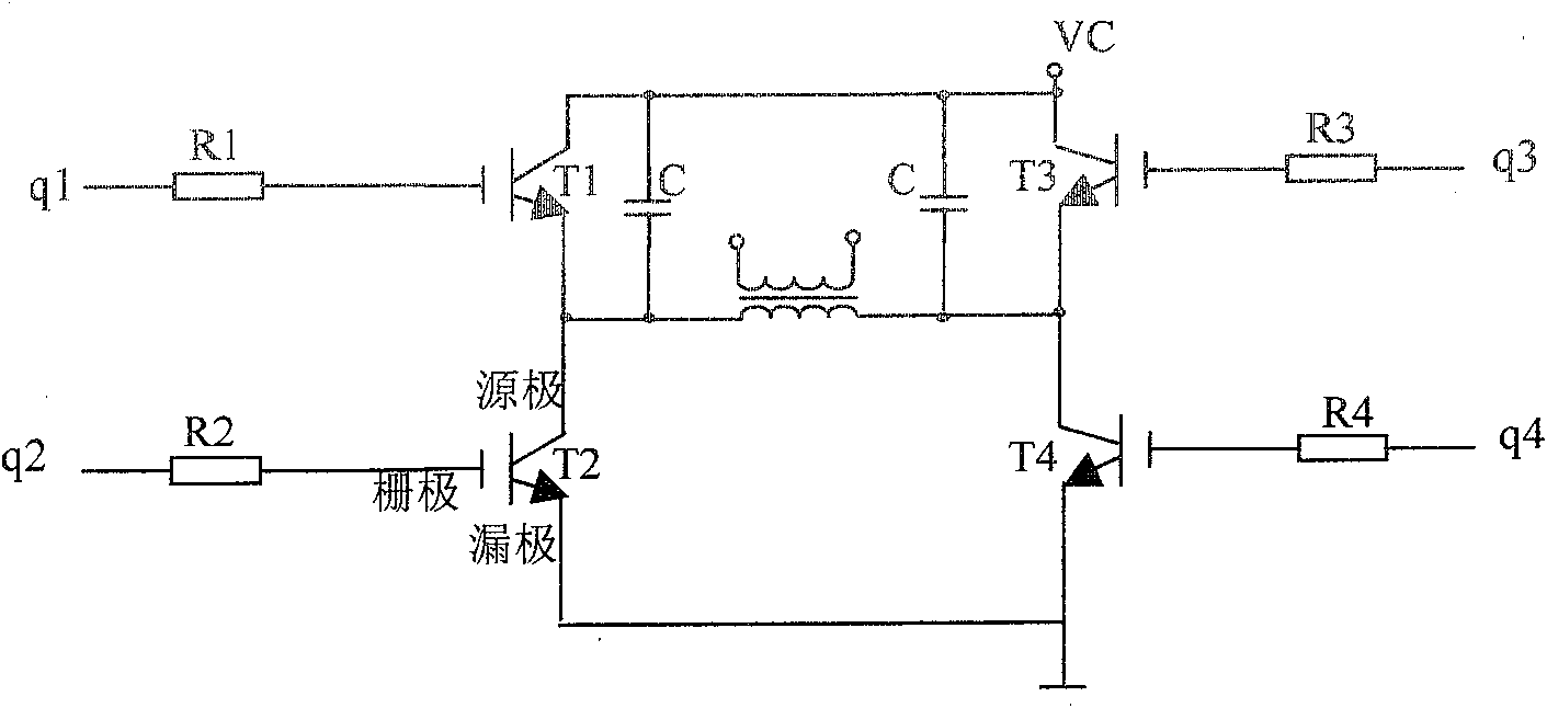
[0019] See attached figure 1 .

[0020] The main circuit of the IGBT full-bridge inverter power supply includes four bridge arms composed of four IGBT tubes T1, T2, T3, T4, low-impedance drive sources q1, q2, q3, q4, output main transformer, and IGBT tubes T1, T2 The bases of , T3 and T4 are respectively connected in series with driving resistors R1 , R2 , R3 , R4 , and two IGBT tube collector and emitter bypass capacitors C.

[0021] That is, R1=R3=a; R2=R4=b; parameter selection a=1.2~5b, a=1.2Ω~500Ω, b=1Ω~100Ω, the collectors and emitters of the two IGBT tubes T1 and T3 are bypassed respectively Capacitance C, capacitance C=200pF~10000pF.

example 2

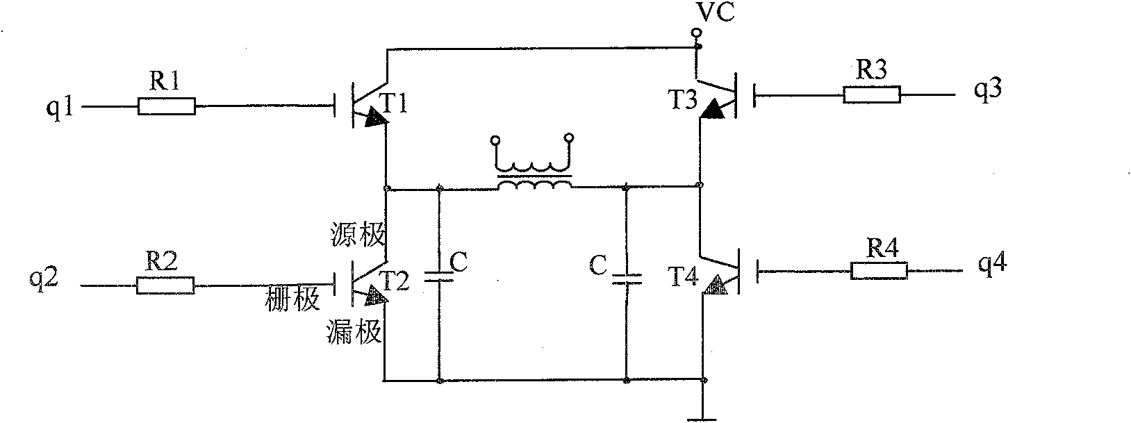
[0023] see figure 2 .

[0024] That is, R1=R3=a; R2=R4=b; parameter selection b=1.2~5a, a=1Ω~100Ω, b=1.2Ω~500Ω, the collectors and emitters of the two IGBT tubes T2 and T4 are bypassed respectively Capacitance C, capacitance C=200pF~10000pF.

example 3

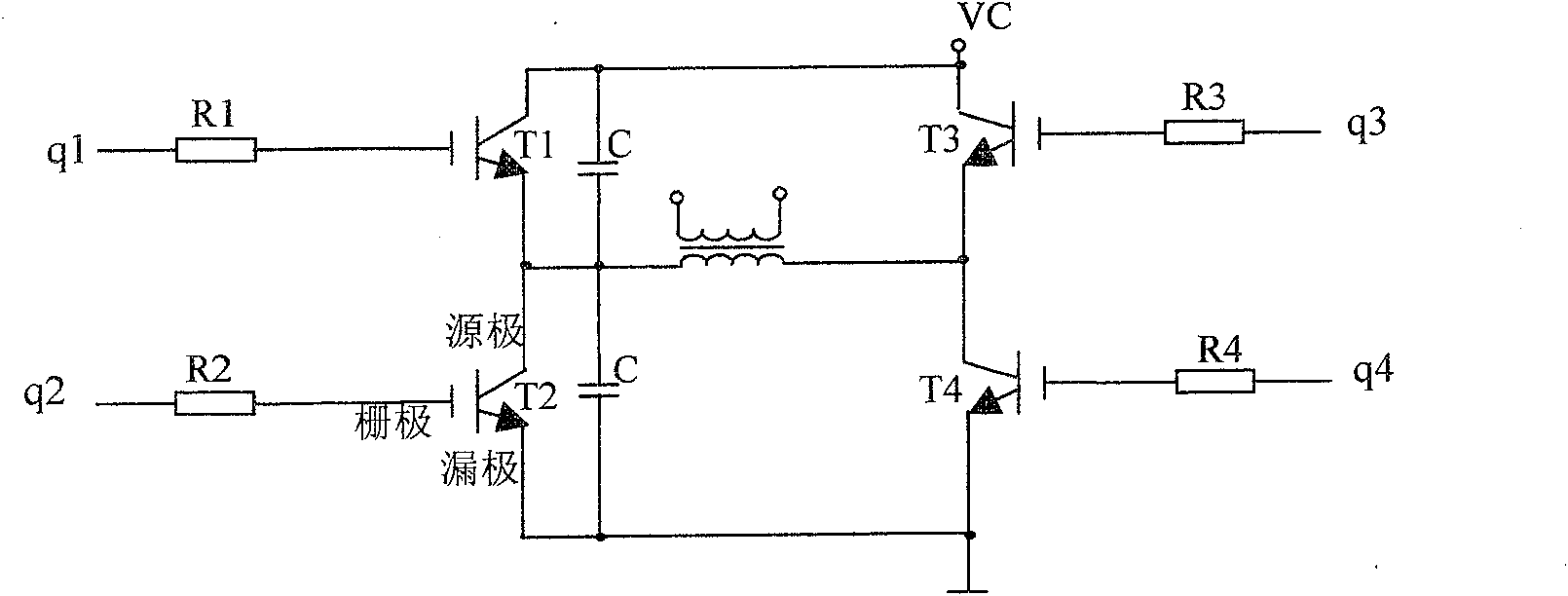
[0026] see image 3 .

[0027] That is, R1=R2=a; R3=R4=b; parameter selection a=1.2~5b, a=1.2Ω~500Ω, b=1Ω~100Ω, the collectors and emitters of the two IGBT tubes T2 and T4 are bypassed respectively Capacitance C, capacitance C=200pF~10000pF.


PUM


Abstract

The invention is concerned with a kind of IGBT full bridge invert power source, relating to four bridge arms made of four IGBT tubes, drive power with low resistance and main output transformer. The grids of T1,T2,T3,T4 to IGBT tubes have drive resistances of R1,R2,R3,R4 in series, and the IGBT drive resistance of the said closed or diagonal bridge arms is different, there are equal capacitances C on both bypasses of the two IGBT tube source and leak pole with larger value of drive resistance, the R1 and R3 are equal to a, R2 and R4 are equal to b or R1 and R2 are equal to a, R3 and R4 are equal to b, while a is equal to (1+beta)b or b is equal to (1+beta)a, betais 20 to 400 percent, and the capacitances C is 200 pF to 10000 pF. The main circuit structure uses full bridge invert power source and unique parameter to perfectly cooperate with main output and main transformer and enhance the reliability of IGBT switch.

Description

Technical field: [0001] The invention belongs to an inverter power supply, in particular to an improved IGBT full-bridge drive and a main circuit for related conversion power supplies. Background technique: [0002] As a high-power industrial power supply, IGBT inverter power supply can be widely used in various industries, such as electroplating, point solution industry, welding and cutting industry, etc., which has become the basis of our social development. Traditional industrial power supplies are mostly silicon-controlled rectifiers, or autotransformers to adjust the output. In contrast, the IGBT inverter power supply has the advantages of small size, light weight, high output efficiency and energy saving and material saving, which has brought revolutionary changes to the traditional industrial power supply industry and is called "tomorrow's power supply". However, the IGBT inverter power supply circuit is complex, and if the parameters of each component are not design...

Claims


Application Information

Patent Timeline
Patent Type & Authority Patents(China)
IPC IPC(8): H02M7/5387
Inventor 袁忠杰
Owner 袁忠杰
Learn More