Indicating system of the space length between the left and right vehicle wheel tyres

A vehicle, left and right technology, applied in the field of vehicle left and right tire spacing indication systems, can solve the problems of not fully complying with the viewing angle, the laser beam transmitter has no pitch angle adjustment mechanism, etc.

Inactive Publication Date: 2009-12-02
徐 世龙
View PDF6 Cites 0 Cited by
  • Summary
  • Abstract
  • Description
  • Claims
  • Application Information

AI Technical Summary

Problems solved by technology

[0004] However, the laser beam transmitter of this guidance system does not have an adjustment mechanism for the pitch angle. The main reason is that drivers of different heights can look up at different distances from the driver's seat. Therefore, in this case, the laser beam The visible light beams projected by the beam emitters do not fully conform to the perspectives of drivers of different heights. In this way, it is even more difficult to observe the width of the road or the size of potholes and obstacles more accurately at close range. up

Method used


Image

  • Indicating system of the space length between the left and right vehicle wheel tyres
  • Indicating system of the space length between the left and right vehicle wheel tyres
  • Indicating system of the space length between the left and right vehicle wheel tyres

Examples


Embodiment Construction

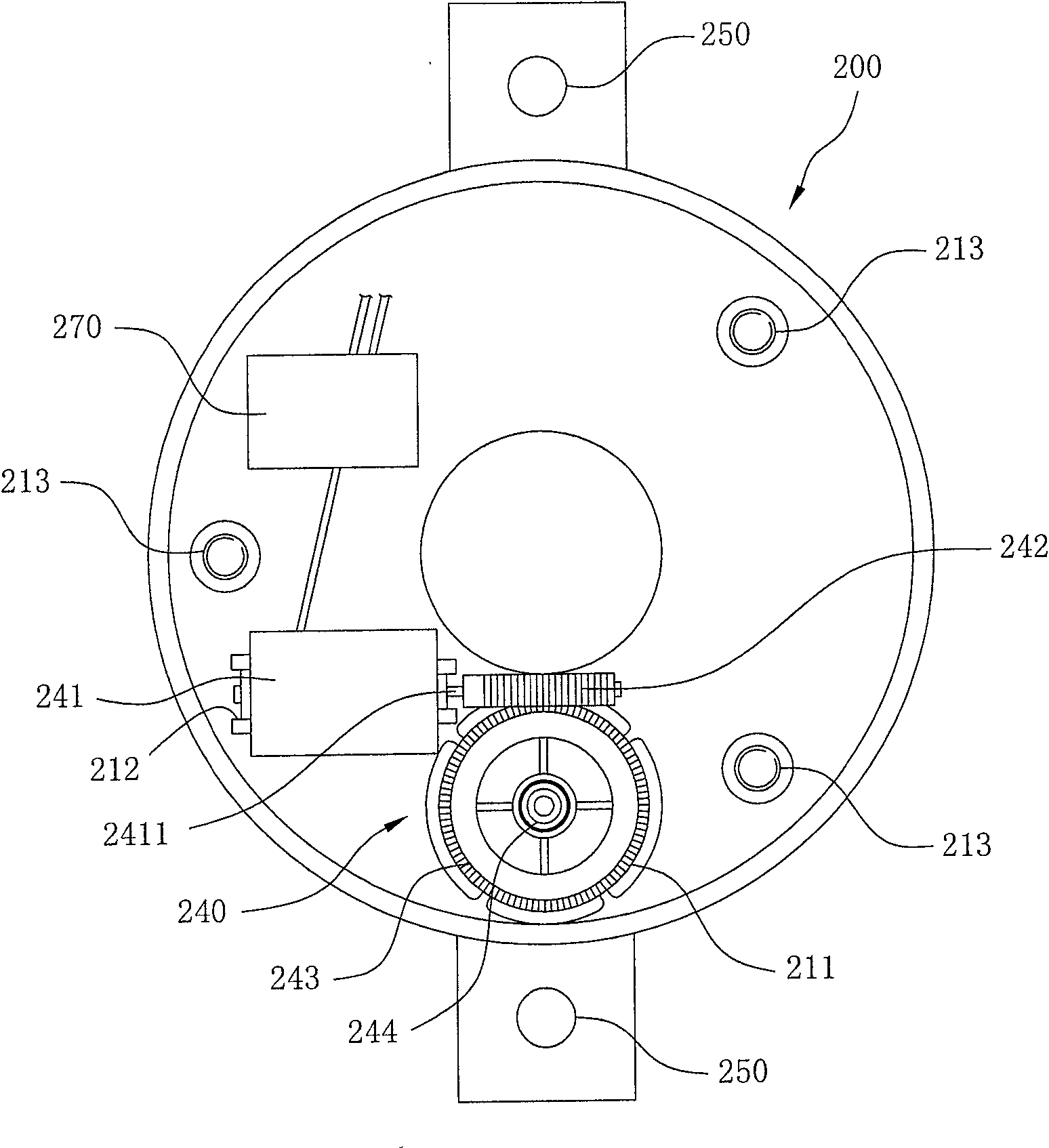
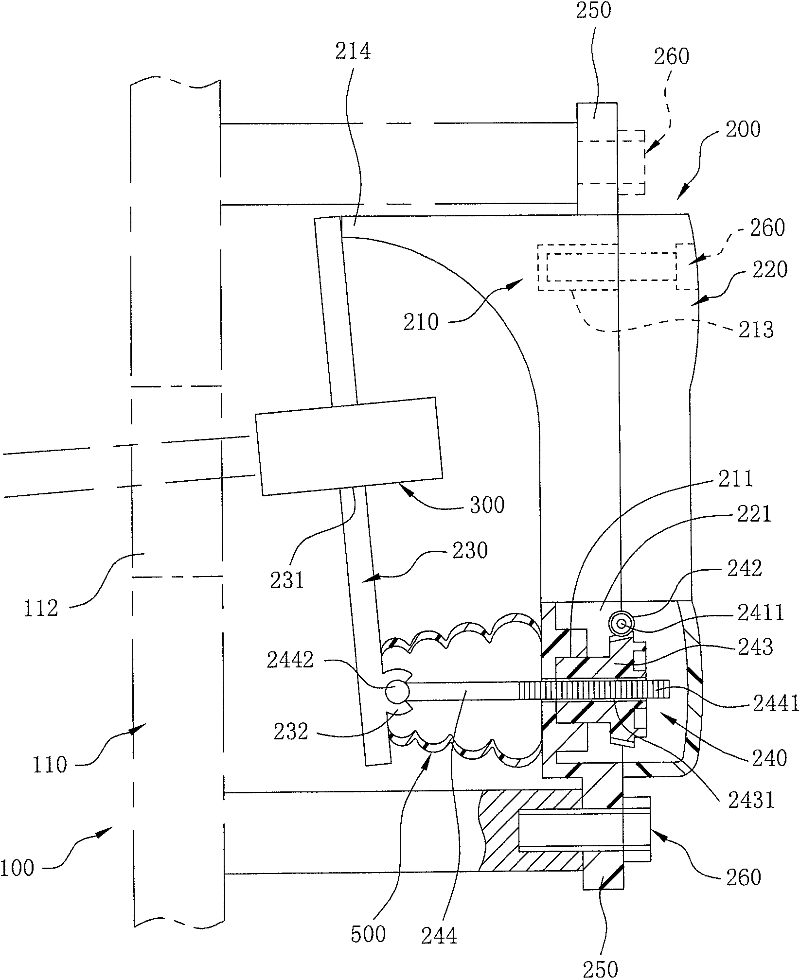
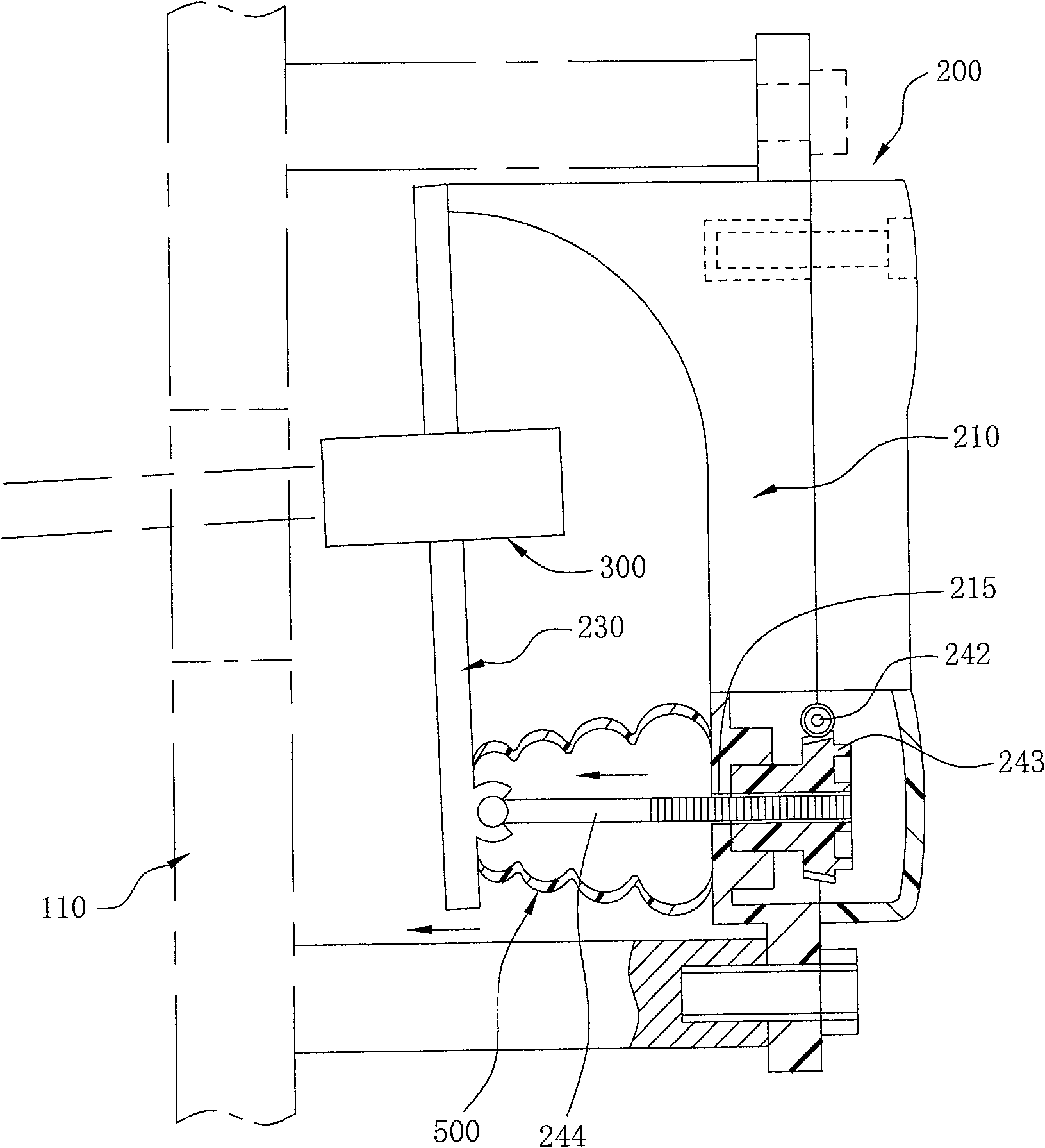
[0018] refer to figure 1 and figure 2 , are respectively a partial top view and a combined side view of an embodiment of the present invention.

[0019] This embodiment of the vehicle left and right tire distance indicating system of the present invention is installed on a front bumper 110 on the front side of a vehicle 100 (also can be installed on the rearview mirror), and faces the vehicle 100 front. The vehicle left and right tire spacing indicating system includes two adjusting devices 200 respectively installed on both sides of the front of the vehicle 100, and at least two groups of pointing units 300 (since the structures of the two adjusting devices 200 and the two pointing units 300 are the same, so figure 1 and figure 2 Only a single adjusting device 200 and a single pointing unit 300 are shown in the figure).

[0020] refer to Figure 4 , which is a circuit diagram of the present invention.

[0021] refer to figure 1 , figure 2 and Figure 4 , the adjust...


PUM


Abstract

A vehicle left and right tire spacing indicating system includes two adjusting devices respectively installed on both sides of the front of the vehicle and at least two sets of pointing units. The adjustment device has a base, a movable part pivotally connected to one side of the base, and an angle control unit installed between the base and the movable part. The pointing unit is installed on the movable part, and the angular displacement of the movable part is regulated by the angle control unit, so that the pointing unit on it changes with the pitch angle of the movable part, thereby changing the far and near distance of the light beam Projection effect.

Description

technical field [0001] The present invention relates to a device for projecting light beams, and in particular to an indicator system for indicating the distance between left and right tires of a vehicle for drivers to judge the distance between left and right tires of the vehicle. Background technique [0002] In the process of driving, if there are potholes or protruding obstacles on the road ahead, if the potholes and protruding obstacles are not too large, the driver can usually dodge and pass by visually. However, it is not a good strategy to observe obstacles in front of you purely by feeling. Because, of course, there will be no doubts about visual errors for smaller obstacles. When the potholes and obstacles are neither big nor small, and are very close to the minimum distance between the left and right tires, at this time, observing the size of the obstacle by feeling will sometimes cause difficulties and obstacles for the driver in controlling the vehicle, especia...

Claims


Application Information

Patent Timeline
Patent Type & Authority Patents(China)
IPC IPC(8): B62D15/02B60R16/02G01B11/14
Inventor 徐世龙
Owner 徐 世龙
Why Eureka
Try Eureka