Optical collimator

A technology of optical collimation and optical fiber, which is applied in the direction of coupling of optical waveguides to achieve the effect of reducing diameter

Inactive Publication Date: 2009-11-18
NIPPON ELECTRIC GLASS CO LTD
View PDF11 Cites 0 Cited by
  • Summary
  • Abstract
  • Description
  • Claims
  • Application Information

AI Technical Summary

Problems solved by technology

[0026] In this way, when using conventional optical collimators to perform alignment work between optical collimators, each optical collimator is only placed on, for example, one V-groove so that each set of optical collimators is placed at a position that becomes their working distance. The central axes of the outer peripheral surfaces of the cylinders face each other in the same state, so that when light is introduced from one optical fiber, sufficient optical response cannot be obtained from the other optical fiber

Method used


Image

  • Optical collimator
  • Optical collimator
  • Optical collimator

Examples


Embodiment Construction

[0051] Hereinafter, embodiments of the present invention will be described with reference to the drawings.

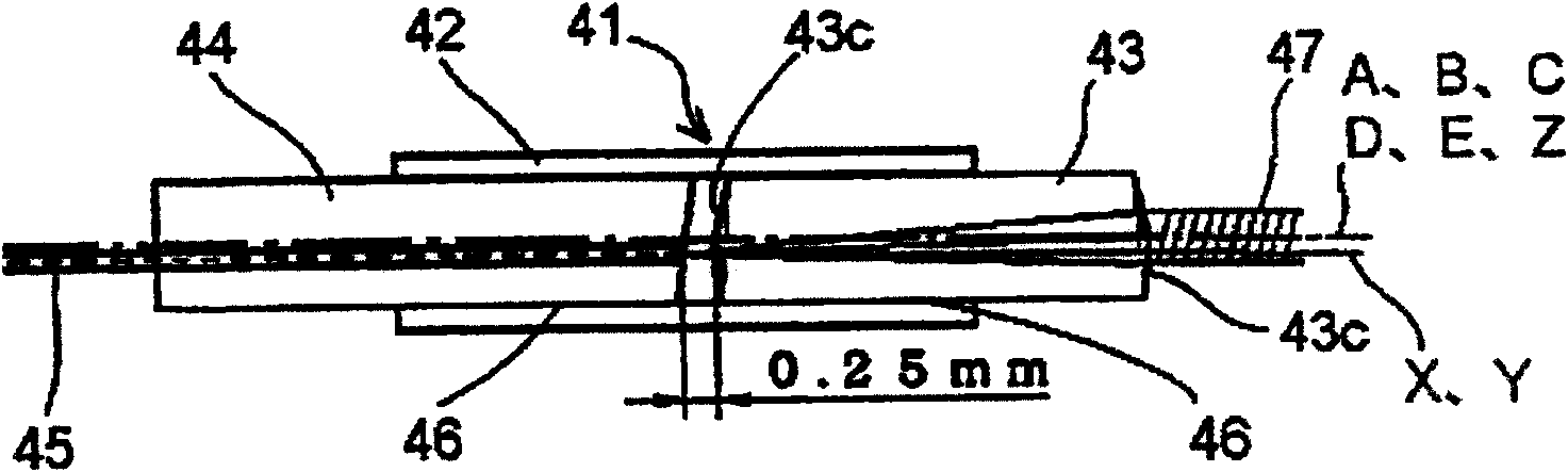
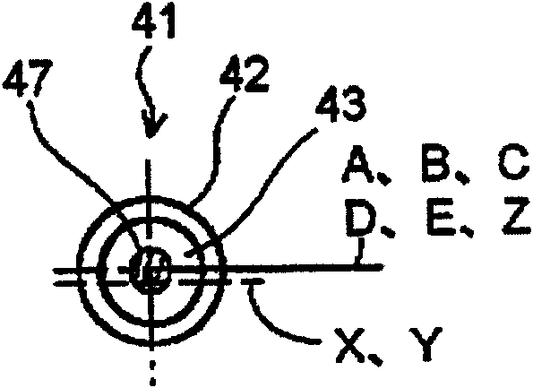
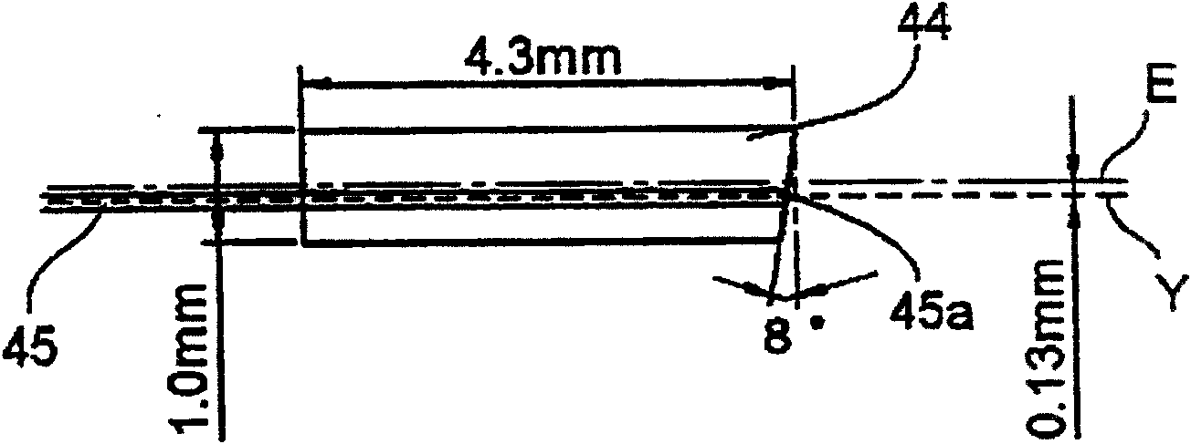
[0052] As shown in FIGS. 1 to 4 , the optical collimator 41 of this embodiment has a cylindrical sleeve 42 , a partially spherical lens 43 , and a capillary 44 . The sleeve 42 has an inner hole 42a at its center. The partially spherical lens 43 has a light-transmitting spherical surface 43c with substantially the same center of curvature at the two ends 43b of a cylindrical portion 43a made of glass with approximately uniform refractive index. When inserted into and fixed in the inner hole 42a of the sleeve 42, A position eccentric by a predetermined amount from the central axis B of the outer peripheral surface of the sleeve 42 becomes the optical axis X. The capillary 44 fixes the optical fiber 45 at a position eccentric by a predetermined amount with respect to the central axis B of the outer peripheral surface of the sleeve 42 when inserted and fixed into the inner...


PUM


Abstract

The light collimator has a sleeve, a partially spherical lens, and a capillary holding an optical fiber. The sleeve has an inner bore concentric with its outer peripheral surface. The partially spherical lens has a cylindrical part inserted into the inner hole of the sleeve and light-transmitting spherical surfaces arranged at both ends of the cylindrical part. The optical axis of the transparent spherical surface is located at a position eccentric to the central axis of the outer peripheral surface of the sleeve. The capillary is inserted into the inner hole of the sleeve, the optical fiber is fixed at a position eccentric to the central axis of the outer peripheral surface of the sleeve, and the inclined end surface of the optical fiber is directed toward the partially spherical lens.

Description

technical field [0001] The invention relates to a light collimator with a capillary, a partially spherical lens and a sleeve. An optical fiber for optical communication is fixed inside the capillary. The partially spherical lens has a cylindrical part and a light-transmitting spherical surface, and the sleeve, Coaxial with capillary and partially spherical lens. Background technique [0002] When constructing a high-speed and large-capacity optical fiber communication system, many optical devices are used, including taking out an optical signal of any wavelength from multiple wavelength-complexed optical signals, and using optical crystals that make the phases of optical signals consistent, etc. , in order to convert the optical signal emitted from the optical fiber and spread into parallel light, or to collect the parallel light in the optical fiber, multiple optical collimators are used. [0003] As shown in Fig. 6, in the past, the optical collimator 1 using a partially ...

Claims


Application Information

Patent Timeline
Patent Type & Authority Patents(China)
IPC IPC(8): G02B6/32
Inventor 田中宏和角见昌昭
Owner NIPPON ELECTRIC GLASS CO LTD
Why Eureka
Try Eureka