
Large turn angle ball support

A corner ball, upper seat technology, applied in the direction of building, building structure, etc., can solve the problems of small horizontal force deformation, small turning angle, increased engineering cost, etc., to achieve the effect of improving sealing, reducing friction, and preventing oil spillage

Active Publication Date: 2009-09-30
丰泽智能装备股份有限公司
View PDF6 Cites 0 Cited by
  • Summary
  • Abstract
  • Description
  • Claims
  • Application Information

AI Technical Summary

Problems solved by technology

[0002] At present, rubber bearings are mostly used between the roof and pillars of grid buildings to connect and transmit vertical loads and horizontal forces, and to meet the horizontal force and rotation angle requirements required by the deformation of the upper structure. Due to the allowable pressure of rubber bearings The stress is small and the allowable deformation is small, so its bearing capacity is small, the rotation angle is small, and the horizontal force deformation is small. It is only suitable for grid frames with small spans (spans less than 30 meters). For large-span grid structure buildings, rubber bearings It has not met the requirements, and people use to increase the rigidity of the grid to reduce the corner and horizontal force of the rubber bearing due to the self-weight and temperature changes of the upper structure, which increases the project cost.
Later, people used steel bearings. Since the upper seat plate adopts an "I"-shaped structure, the upper edge and lower side of the base are in contact with the upper seat plate plane. contact, the downward pressure is uniform, but the pulling force is uneven, which reduces the service life; and the rotation range of the upper seat plate is limited by the gap between its side and the base, so the rotation angle is small (generally less than 0.02 radians), which is not suitable for large Corner requirements

Method used


Image

  • Large turn angle ball support

Examples


Embodiment Construction

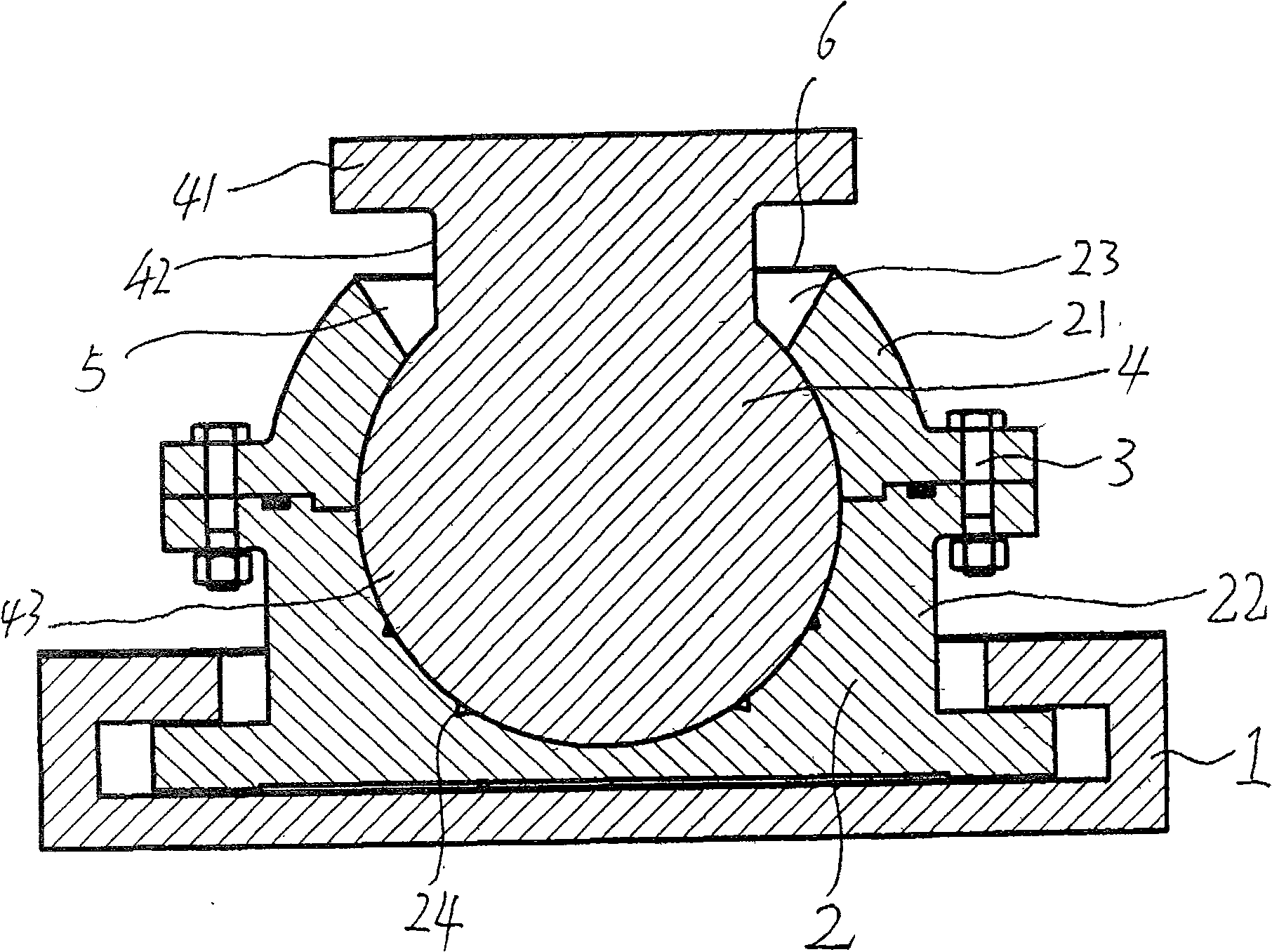
[0007] The structure and operating principle of a large-corner ball bearing of the present invention will be further described in detail below in conjunction with the accompanying drawings.

[0008] As shown in the accompanying drawings, it is a structural schematic diagram of a longitudinal section of a large corner ball bearing of the present invention. A large corner ball bearing of the present invention includes a box body 1 and a base 2 in the box body. The inner wall of the base 2 is a spherical surface with an upper seat plate opening 23 on the upper part. The base 2 is composed of an upper base 21 and a lower base 22. The upper base 21 and lower base 22 are connected together by screw rod 3, and upper seat plate 4 is arranged in base 2, and upper seat plate 4 comprises upper seat plate shoulder 41, upper seat plate waist 42 and upper seat plate lower shoulder 43, upper seat plate shoulder 41 is a square plate shape, the upper seat plate waist 42 is cylindrical, the upp...


PUM


Abstract

The invention belongs to the technical field of bearings, and in particular relates to a large corner ball bearing. It includes a box body and a base in the box, an upper seat plate is arranged in the base, the inner wall of the base is a spherical surface with an upper seat plate mouth on the upper part, the base is composed of an upper base and a lower base, the upper seat plate It includes the shoulder of the upper seat, the waist of the upper seat and the lower shoulder of the upper seat. The lower shoulder of the upper seat is a spherical convex that matches the spherical surface of the inner wall of the base. An interval is set between the edge of the upper seat plate mouth and the waist of the upper seat plate, an annular oil storage tank is arranged on the inner wall of the base, an annular sealing cover plate is arranged on the upper surface of the base, and the upper base and The contact surface of the lower base is stepped. It solves the problems of small rotation angle, small bearing capacity, uneven pulling force and short service life of the current bearing. It can be widely used between the top and pillars of grid structure buildings.

Description

technical field [0001] The invention belongs to the technical field of bearings, and in particular relates to a large-corner ball bearing. Background technique [0002] At present, rubber bearings are mostly used between the roof and pillars of grid buildings to connect and transmit vertical loads and horizontal forces, and to meet the horizontal force and rotation angle requirements required by the deformation of the upper structure. Due to the allowable pressure of rubber bearings The stress is small and the allowable deformation is small, so its bearing capacity is small, the rotation angle is small, and the horizontal force deformation is small. It is only suitable for grid frames with small spans (spans less than 30 meters). For large-span grid structure buildings, rubber bearings It has not met the requirements, and people use to increase the rigidity of the grid to reduce the corner and horizontal force of the rubber bearing due to the self-weight and temperature chan...

Claims


Application Information

Patent Timeline
Patent Type & Authority Patents(China)
IPC IPC(8): E04B1/36E04B1/38
Inventor 张培基王立志
Owner 丰泽智能装备股份有限公司
Learn More